.
Garage Door Monitor with Cayenne Reviewed by Unknown on 17:14 Rating: 4.5

Garage Door Monitor with Cayenne


Description

Using the HMC5883L magnetometer sensor of the GY-80 module from ICStation to monitor a garage door and notify when it has been opened or closed. The Cayenne service provides much of the monitoring and notifying functionality. A major feature of this project. Cayenne takes care of all of the complicated work behind the scenes, making it easy to connect your Arduino to the cloud and allow you to monitor your garage from virtually anywhere.
 
This project was created specifically to monitor a garage, but you will soon discover that this project could be used to monitor a whole host of other things. Monitor your front door, your back door, your bag, your chair, your cookie jar.
 
Monitor for peace of mind, or catch someone in the act of stealing your stuff. This project has got you covered. Let's see how:


HMC5883L DataSheet:

You can find the datasheet for the HMC5883L pretty easily by searching on the internet.
HMC5883L datasheet - Sparkfun


Arduino Libraries and IDE

Here is a link to the Arduino IDE download. The IDE is required to upload code to the Seeeduino Cloud.

You need the Cayenne Library installed in your Arduino IDE.
You can find the Cayenne library here:
Cayenne Libarary
 
There are libraries on the internet for the GY-80 module, however, it is relatively easy to use the magnetometer on this module. And therefore no libraries are required for the sensor. If you would like some more information about using the magnetometer sensor, and how to get the most out of it, then please have a look at my previous tutorial which goes into much more detail.


ARDUINO CODE:


You need to make sure to insert your OWN Cayenne token into the sketch above. You will get this token when connecting your Arduino to the Cayenne service. Watch the video for further explanation.


Fritzing diagram

Cayenne Widgets

Please make sure to watch the video to see how to connect the Seeeduino Cloud to Cayenne and how to create the Cayenne widgets. Cayenne widgets are necessary to create the dashboard on your phone or browser. They will also interact with the Arduino sketch, and will also be involved in creating the notification system. The following links will take you to the relevant part of the video:

The Master switch button is used to switch monitoring from OFF to ON (and vice versa). Therefore you can choose when to monitor the garage and when to stop monitoring. When first installing the project onto your garage door, and turning the Seeeduino Cloud on, it will automatically calibrate each sensor to a value of 1000.
 
If you experience any drift away from 1000 for whatever reason, simply press the Request calibration button, and each sensor will be recalibrated back to 1000. The x,y and z axis widgets are there so that you can see the readings coming from the magnetometer sensor. And when any of the axis variables breach the threshold away from 1000, it will trigger the Door Status widget. This is how we can tell if the door is open or closed.
 
We also use the Door Status widget to help with the notification system. When the Door status changes from "Closed" to "Open", a notification trigger will be activated, and a message will be sent via email or SMS. This notification is useful for monitoring when the door was opened. If you happen to recalibrate when the door is open. You will get a notification when the garage door closes.


Concluding comments

This project is relatively simple, and quite easy to set up. What I liked about this project was the versatility and alternate uses. You can use the same setup to monitor many different things. It is not just limited to monitoring a garage door. But being able to tell whether my garage door is opened or closed, especially after I have driven away from my house , is really cool. Now I don't have to drive all the way back home to check. Let me know if you have replicated this project, and also what kinds of things you decided to monitor with this project.

Description: Garage Door Monitor with Cayenne Rating: 3.5 Reviewer: Unknown ItemReviewed: Garage Door Monitor with Cayenne
MT8870 DTMF - Dual Tone Multi Frequency Decoder Reviewed by Unknown on 22:51 Rating: 4.5

MT8870 DTMF - Dual Tone Multi Frequency Decoder

Project Description

We will be using an MT8870 DTMF module with an Arduino UNO to control a small servo motor in this project. The DTMF module gives the Arduino super-powers and allows you to control the Servo motor in so many ways. For example, this tutorial will show you how to control the servo motor using:
  • a YouTube Video
  • a voice recorder
  • A web application (Online tone generator)
  • A smart phone app (DTMF Pad)
  • A touch-tone phone to cell-phone call
All of these control methods will take advantage of the same exact Arduino code/sketch. But how???
The MT8870 DTMF decoder is quite a neat little module that allows you incorporate DTMF technology into your arduino projects. DTMF stands for Dual-Tone Multi-Frequency. DTMF tones are commonly associated with touch-tone phones and other telecommunication systems. When you press the number "1" on a touch-tone phone, two sine waves with frequencies: 697Hz and 1209Hz are combined to produce a unique DTMF signal which can be transmitted through the phone line. The MT8870 DTMF module can take this signal as an input, and decode it to produce a binary output.


The DTMF module does not care how you produce the DTMF tone. However, if it receives this tone, it will decode it. We can take advantage of this feature to supply the module with tones from different sources. The module has a 3.5mm port for line input. Providing you can connect your DTMF source to this line input in some way, it should work. I must warn you, however that this is a line input and NOT a microphone input. If you wanted to use a microphone, you will need to boost or amplify the signal before sending it to the DTMF module.
 
You will need the following parts for this project
 

Parts Required:

Software/Apps Required

Arduino Sketch


Upload the following sketch to the Arduino.
 

1
2
3
4
5
6
7
8
9
10
11
12
13
14
15
16
17
18
19
20
21
22
23
24
25
26
27
28
29
30
31
32
33
34
35
36
37
38
39
40
41
42
43
44
45
46
47
48
49
50
51
52
53
54
55
56
57
58
59
60
61
62
/* ================================================================================================================================================== Project: MT8870 DTMF Servo sketch Author: Scott C Created: 4th August 2015 Arduino IDE: 1.6.4 Website: http://arduinobasics.blogspot.com/p/arduino-basics-projects-page.html Description: This project will allow you to control a Servo motor using an Arduino UNO and a MT8870 DTMF Module. The DTMF signal is received through the 3.5mm port of the DTMF module and is decoded. We will use the decoded output to control the position of the Servo. A SG-5010 Servo motor was used in this project. ===================================================================================================================================================== *///This sketch uses the Servo library that comes with the Arduino IDE #include <Servo.h> //Global variables----------------------------------------------------------------------------------------- Servo SG5010; // The SG5010 variable provides Servo functionality int servoPosition = 0; // The servoPosition variable will be used to set the position of the servo byte DTMFread; // The DTMFread variable will be used to interpret the output of the DTMF module. const int STQ = 3; // Attach DTMF Module STQ Pin to Arduino Digital Pin 3 const int Q4 = 4; // Attach DTMF Module Q4 Pin to Arduino Digital Pin 4 const int Q3 = 5; // Attach DTMF Module Q3 Pin to Arduino Digital Pin 5 const int Q2 = 6; // Attach DTMF Module Q2 Pin to Arduino Digital Pin 6 const int Q1 = 7; // Attach DTMF Module Q1 Pin to Arduino Digital Pin 7 /*========================================================================================================= setup() : will setup the Servo, and prepare the Arduino to receive the MT8700 DTMF module's output. ========================================================================================================== */void setup() { SG5010.attach(9); // The Servo signal cable will be attached to Arduino Digital Pin 9 SG5010.write(servoPosition); // Set the servo position to zero. //Setup the INPUT pins on the Arduino pinMode(STQ, INPUT); pinMode(Q4, INPUT); pinMode(Q3, INPUT); pinMode(Q2, INPUT); pinMode(Q1, INPUT);} /*========================================================================================================= loop() : Arduino will interpret the DTMF module output and position the Servo accordingly ========================================================================================================== */void loop() { if(digitalRead(STQ)==HIGH){ //When a DTMF tone is detected, STQ will read HIGH for the duration of the tone. DTMFread=0; if(digitalRead(Q1)==HIGH){ //If Q1 reads HIGH, then add 1 to the DTMFread variable DTMFread=DTMFread+1; } if(digitalRead(Q2)==HIGH){ //If Q2 reads HIGH, then add 2 to the DTMFread variable DTMFread=DTMFread+2; } if(digitalRead(Q3)==HIGH){ //If Q3 reads HIGH, then add 4 to the DTMFread variable DTMFread=DTMFread+4; } if(digitalRead(Q4)==HIGH){ //If Q4 reads HIGH, then add 8 to the DTMFread variable DTMFread=DTMFread+8; } servoPosition = DTMFread * 8.5; //Set the servoPosition varaible to the combined total of all the Q1 to Q4 readings. Multiply by 8.5 to amplify the servo rotation. } SG5010.write(servoPosition); //Set the servo's position according to the "servoPosition" variable. }


Fritzing Sketch


Connect the Arduino to the MT8870 DTMF module, and to a Servo.
Use the following Fritzing sketch as a guide.
 
(Click the image above to enlarge it)


Discussion


You will need to connect a cable from the DTMF module's 3.5mm port to that of your smart phone, computer, voice recorder or any other DTMF source of your choice.


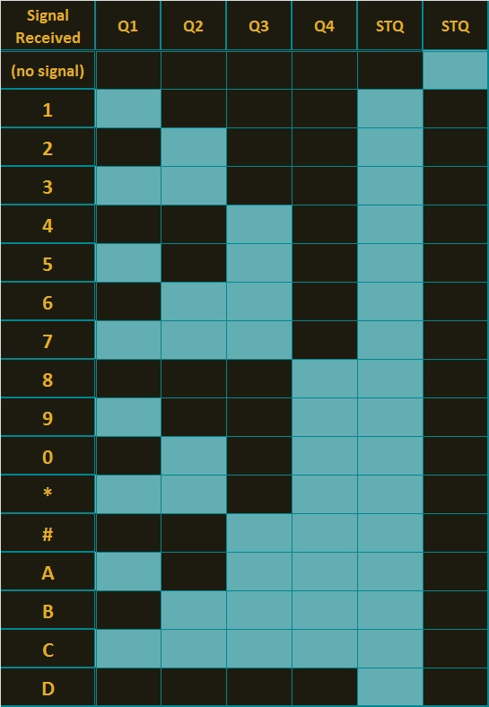
When you power up your Arduino, the Servo motor should turn all the way to the left to it's zero position. Once the DTMF module receives a DTMF signal, it will identify the relevant frequecies as described in the table at the beginning of this tutorial, and produce a binary like output. You will notice the DTMF module's onboard LEDs light up when a tone is detected. Onboard LED (D5) will turn on for the length of the DTMF tone it just received, and turn off when the tone has stopped. On the other hand, the onboard LEDs (D1 to D4) will light up depending on the tone received, and will remain lit until the module receives another tone. The onboard LEDs are a visual representation of the voltages applied to the DTMF module's pins (Q1 to Q4, and STQ). Q1 matches D1, Q2 matches D2 etc etc. and STQ matches D5.
 
You will notice that there are two STQ pins on the DTMF module. The STQ pin that is closest to Q4 will only go high when a DTMF tone is detected, and will remain high for the duration of the tone. The other STQ pin is the exact opposite. It will switch LOW when a tone is received and remain LOW for the duration of the tone. When there is no tone, this STQ pin will remain HIGH. The table below provides a summary of the DTMF module outputs, with a blue box representing a voltage applied to that pin (HIGH), whereas a black box indicates no voltage applied (LOW).


In order to follow this project, you need a source of DTMF tones. You can produce DTMF tones using a touch-tone phone, or through the use of a DTMF Pad app. If you are feeling creative, you can create a DTMF song/tune like the one I posted on YouTube. You can see the video below:


As you can see from the video, I also recorded the DTMF tune onto a voice recorder, and was able to control the servo that way. If you are not feeling creative, you can visit this website to create DTMF tones from your browser.

Concluding comments


This project was very fun, and shows some novel ways to control your Arduino. After completing the project, I realised that I could use this module to alert me when new emails or messages arrive on my phone or computer. If you have the ability to change the email or message notification sound to a DTMF tone, you should be able to get the module and Arduino to respond accordingly. Oh well, maybe I'll save that project for another day.
 
If this project helped you in anyway or if you use my code within your project, please let me know in the comments below. I would be interested to see what you did.


If you like this page, please do me a favour and show your appreciation :

 
Visit my ArduinoBasics Google + page.
Follow me on Twitter by looking for ScottC @ArduinoBasics.
I can also be found on Pinterest and Instagram.
Have a look at my videos on my YouTube channel.


However, if you do not have a google profile...
Feel free to share this page with your friends in any way you see fit.


Description: MT8870 DTMF - Dual Tone Multi Frequency Decoder Rating: 3.5 Reviewer: Unknown ItemReviewed: MT8870 DTMF - Dual Tone Multi Frequency Decoder
Sound Sensor Reviewed by Unknown on 23:07 Rating: 4.5

Sound Sensor


This project makes use of Seeedstudio's Grove Sound Sensor. Which essentially gives your Arduino ears ! The small sound sensor (microphone) attaches to an Analog pin on the Arduino and can be used to detect the level of noise in the surrounding environment. You could potentially use this sensor to turn a light on in your house after recognising a specific clap/whistle sequence. In this tutorial we are going to connect a few LEDs to the Arduino, and get it to listen for a click/clap, and respond accordingly. Have a look at the video below for this project in Action.


Parts Required


Assembly

  • Place the Grove Base shield onto the Arduino UNO or compatible microcontroller.
  • Solder some headers onto a ProtoBoard and then stack this onto the Grove Base Shield
  • Stick a Mini-Bread board onto the ProtoBoard.
  • Get 3 LEDs and 330 ohm resistors, connect to Pins 3, 5 and 6, and then to Ground
  • Attach the Sound Sensor to the Grove Base Shield A0 clip (next to shield's reset button) 


Sketch


Arduino LogoArduino Code:

 1
2
3
4
5
6
7
8
9
10
11
12
13
14
15
16
17
18
19
20
21
22
23
24
25
26
27
28
29
30
31
32
33
34
35
36
37
38
39
40
41
42
43
44
45
46
47
48
49
50
51
52
53
54
55
56
57
58
59
60
61
62
63
64
65
66
/* =======================================================
ArduinoBasics: Sound Sensor: Written by ScottC 8th May 2013
==========================================================*/

int soundSensorPin=A0;
int soundReading=0;
int soundThreshold=500;
int intensity[3]={0,0,0};
int LEDPins[3] = {3,5,6};
int numberOfPins=3;
int currentPin=0;
int fadeCounter=0;
int fadeDelay=50;
boolean switcher = true;

void setup(){
pinMode(soundSensorPin, INPUT);
for(int i=0; i<numberOfPins;i++){
pinMode(LEDPins[i],OUTPUT);
}
}

void loop(){
soundReading=analogRead(soundSensorPin);
if(soundReading>soundThreshold){
if(switcher){
aboveThreshold(currentPin);
switcher=true;
}
} else {
if(switcher){
belowThreshold();
switcher=true;
}
}
}

void aboveThreshold(int cPin){
switcher=false;
if(intensity[cPin]<10){
intensity[cPin]=255;
delay(50);
currentPin=currentPin+1;
}

if(currentPin==numberOfPins){
currentPin=0;
}
}

void belowThreshold(){
switcher=false;
fadeCounter++;
if(fadeCounter==fadeDelay){
fadeCounter=0;
for(int i=0; i<numberOfPins;i++){
analogWrite(LEDPins[i],intensity[i]);
}
for(int i=0; i<numberOfPins;i++){
intensity[i]--;
if(intensity[i]<0){
intensity[i]=0;
}
}
}
}


Description: Sound Sensor Rating: 3.5 Reviewer: Unknown ItemReviewed: Sound Sensor
Back to top