Using the HMC5883L magnetometer sensor of the GY-80 module from ICStation to monitor a garage door and notify when it has been opened or closed. The Cayenne service provides much of the monitoring and notifying functionality. A major feature of this project. Cayenne takes care of all of the complicated work behind the scenes, making it easy to connect your Arduino to the cloud and allow you to monitor your garage from virtually anywhere.
This project was created specifically to monitor a garage, but you will soon discover that this project could be used to monitor a whole host of other things. Monitor your front door, your back door, your bag, your chair, your cookie jar.
Monitor for peace of mind, or catch someone in the act of stealing your stuff. This project has got you covered. Let's see how:
You can find the datasheet for the HMC5883L pretty easily by searching on the internet. HMC5883L datasheet - Sparkfun
Arduino Libraries and IDE
Here is a link to the Arduino IDE download. The IDE is required to upload code to the Seeeduino Cloud.
You need the Cayenne Library installed in your Arduino IDE. You can find the Cayenne library here: Cayenne Libarary
There are libraries on the internet for the GY-80 module, however, it is relatively easy to use the magnetometer on this module. And therefore no libraries are required for the sensor. If you would like some more information about using the magnetometer sensor, and how to get the most out of it, then please have a look at my previous tutorial which goes into much more detail.
ARDUINO CODE:
You need to make sure to insert your OWN Cayenne token into the sketch above. You will get this token when connecting your Arduino to the Cayenne service. Watch the video for further explanation.
Fritzing diagram
Cayenne Widgets
Please make sure to watch the video to see how to connect the Seeeduino Cloud to Cayenne and how to create the Cayenne widgets. Cayenne widgets are necessary to create the dashboard on your phone or browser. They will also interact with the Arduino sketch, and will also be involved in creating the notification system. The following links will take you to the relevant part of the video:
The Master switch button is used to switch monitoring from OFF to ON (and vice versa). Therefore you can choose when to monitor the garage and when to stop monitoring. When first installing the project onto your garage door, and turning the Seeeduino Cloud on, it will automatically calibrate each sensor to a value of 1000.
If you experience any drift away from 1000 for whatever reason, simply press the Request calibration button, and each sensor will be recalibrated back to 1000. The x,y and z axis widgets are there so that you can see the readings coming from the magnetometer sensor. And when any of the axis variables breach the threshold away from 1000, it will trigger the Door Status widget. This is how we can tell if the door is open or closed.
We also use the Door Status widget to help with the notification system. When the Door status changes from "Closed" to "Open", a notification trigger will be activated, and a message will be sent via email or SMS. This notification is useful for monitoring when the door was opened. If you happen to recalibrate when the door is open. You will get a notification when the garage door closes.
Concluding comments
This project is relatively simple, and quite easy to set up. What I liked about this project was the versatility and alternate uses. You can use the same setup to monitor many different things. It is not just limited to monitoring a garage door. But being able to tell whether my garage door is opened or closed, especially after I have driven away from my house , is really cool. Now I don't have to drive all the way back home to check. Let me know if you have replicated this project, and also what kinds of things you decided to monitor with this project.
Description: Garage Door Monitor with Cayenne
Rating: 3.5
Reviewer: Unknown
ItemReviewed: Garage Door Monitor with Cayenne
EasyEDA RGB5050 LED Scroll Bar
Reviewed by Unknown on
13:09
Rating: 4.5
This is a guest post by the EasyEDA team. I would like to thank EasyEDA for providing this tutorial for everyone to enjoy. All information within this post was provided by EasyEDA.
Description
None of us could deny the fact that we would love with to play with LED’s and lighting stuff. I love to play with LED’s and create attractive lighting effects. This project was a result of such an attempt where I created a stunning RGB light effect using the popular development platform Arduino Nano. Let’s see the circuit, code and instruction on building this project:
No libraries are required for this project. The Arduino IDE can be downloaded from the Arduino website. Here is the download link.
ARDUINO CODE:
Preparing the LED strips
Cut down the LED strips into 10 single pieces. Make sure you cut them into equal halves and make sure that only the copper conduction plate in the strip is cut. Making a wrong cut disrupts the electrical conductivity between the LED’s. After cutting down into separate strips, you will need to connect each strip using a Dupont wire connectors.
I have made a custom control board that incorporates an Arduino Nano. The control board is used to boost the incoming signal from Arduino and lights up the corresponding LED strips.
I used a free Online circuit and PCB designing platform called EasyEDA to develop my control board. It is pretty easy to use especially because of the large library of parts to choose from. Once the design is complete, you have the option to order it through EasyEDA. They offers great prices on custom PCB manufacturing. I have added 10 connection points for 10 LED strips. Each RGB LED strip is controlled by one of the Arduino Nano digital pins.. Transistors Q1,Q2,Q3….Q10 act as a switch for these LED strips for controlling 12V strips via a 5V signal from the Arduino. And switches S1,S2..S4 were added to be able to select the effect on the strip. The schematic can be seen below:
Schematic
You can access the actual EasyEDA schematic by clicking on the image below:
After completing the PCB design, you can click on the Fabrication icon.
You will then have access to the PCB order page which will allow you to download your PCB Gerber files that can be sent to any manufacturer. However it is a lot easier (and cheaper) to order it directly from EasyEDA. Here you can select:
the number of PCBs you want to order
the number of copper layers you need
the PCB thickness
copper weight
and even the PCB color
After you’ve selected all of the options, click “Save to Cart” and complete you order. You will then get your PCBs shipped a few days later.
Connect the LED strips through the connection points in the board. Make sure that you connect these correctly (push the connectors all the way onto the pin), because the chances of a short increase significantly with the number of wires connected. Once all the connections are done all that left is to install your Arduino Nano (pre-programmed with the Arduino code above), and to power the PCB with a 12V power supply.
This is an Arduino based home security project that uses the power of "Cayenne" for extraordinary capabilities.
Cayenne Beta
Cayenne is a new IoT drag and drop platform originally released for the Raspberry Pi, but now available for Arduino. Cayenne makes the task of connecting your Arduino to the internet as simple as possible. All of the complexity of internet connectivity is hidden within the Cayenne library.
You can easily create a Network of Arduinos and build an IoT system which can be managed and operated within the Cayenne dashboard. This dashboard is accessible through your browser or via the Cayenne smart phone app (on IOS or Android).
The feature I liked the most, was the ability to change the position of sensors or actuators on the Arduino without having to re-upload Arduino code. I could manage the changed position from within the Cayenne platform. The other feature that I liked was the ability to setup actions based on custom triggers. You can use Cayenne to trigger a whole range of functions, for example: play a sound, move a motor, light up an LED, or to send alert notifications via email or SMS.
Cayenne is in Beta at the moment, so there are a few minor bugs here and there, but overall - I give it a thumbs up - it is definitely worth checking out.
In order to fully experience this new IoT platform, I decided to create a project to really put it through its paces. This is what my Security Project will need:
It will use two Arduinos, one connected to the internet via an Ethernet shield, and the other via WIFI.
Two detectors - a PIR sensor and a laser trip wire.
If the sensors are tripped, the person has 10 seconds to present an RFID tag to the Grove RFID reader:
If a valid RFID tag is SUCCESSFULLY presented within the time limit, a nice personalised greeting will be played to that person using a Grove - Serial MP3 player
If a valid RFID FAILS to be presented within the time limit, an Alarm will sound, and I will be notified of the intrusion via an SMS alert.
The Cayenne dashboard will show the status of the sensors, and I will have full control over my security system via the web interface (or smartphone app).
The sensors will be attached to a different Arduino to that of the Grove MP3 player and the RFID tag reader, which means that there will have to be some level of communication between the two Arduinos. In fact, the cross communication will be vital to the success of this project.
The following flow diagram shows the Security project process. It is a high level view of the decisions being made by each Arduino in response to various events.
Triggers Flow Diagram
The following flow diagram aims to highlight the various triggers set up within Cayenne to get this Security system to work.
Arduino IDE and Library Downloads
You will need an Arduino IDE to upload code to the Arduino and the Seeeduino Cloud. Here is the link to the Arduino IDE: Arduino IDE - download location
The Cayenne service requires that you download and install the Cayenne Library into your Arduino IDE. You can get the Cayenne Library from here: Cayenne Library File - Download
Cayenne Connectivity Setup
The Seeeduino Cloud needs to be prepared for use with Cayenne. Normal operating/setup instructions can be found here: Seeeduino Cloud WIKI page
Once you have successfully connected Seeeduino Cloud to your WIFI network, you can add it to the Cayenne Dashboard by making the following selections from within the Cayenne Web application:
Add New
Device/Widget
Microcontrollers
Arduino
Ensure Seeeduino Cloud is connected to WIFI network - the select the NEXT button
Select - Arduino Yun: Built-in Ethernet - ticked
Providing you have already installed the Cayenne library as described above - you should be able to copy and paste the code to the Arduino IDE and upload to the Seeeduino Cloud.
If successful, you should see the Arduino Yun board appear within the Cayenne Dashboard. If not, then seek help within the Cayenne forum.
The Arduino UNO with WIZNET 5100 - Ethernet Shield also needs to be prepared with Cayenne
Add New
Device/Widget
Microcontrollers
Arduino
Ensure Arduino is powered, and Ethernet shield is connected to your internet router via an Ethernet cable
Copy and paste the code to the Arduino IDE and upload to the Arduino UNO.
If successful, you should see the Arduino Uno board appear within the Cayenne Dashboard. If not, then seek help within the Cayenne forum.
If you have the Ethernet shield with the WIZNET 5200 chip, then you may need to download a specific Ethernet library in addition to the Cayenne library.
Just follow the instructions within the Automatically generated sketch provided - when you select your specific Arduino/Ethernet/WIFI shield combination. If you need further instructions on connecting your device to Cayenne - then please visit the myDevices website for the online documentation.
ARDUINO CODE (1)
Code for Arduino UNO with Ethernet Shield:
The following code will need to be uploaded to the Arduino UNO:
ARDUINO CODE (2)
Code for Seeeduino Cloud:
The following code will need to be uploaded to the Seeeduino Cloud:
Fritzing diagram (1)
Fritzing diagram for Arduino UNO with Ethernet
Please click on the picture below for an enlarged version of this fritzing diagram
Fritzing diagram (2)
Fritzing diagram for Seeeduino Cloud
Please click on the picture below for an enlarged version of this fritzing diagram
Cayenne Dashboard Setup - GUI
The Arduino code only provides half of the functionality of this project. The Cayenne Dashboard needs to be setup to provide the rest of the functionality. The following instructions will show you how to add each of the widgets required for this Home Security project.
Arduino Ethernet - Master Switch
The master switch allows me to turn the security system on and off. When I turn the MASTER SWITCH ON, the laser beam will turn on, and the sensors will start monitoring the area for intruders. This widget is NOT associated with a physical switch/sensor on the Arduino - it uses virtual channel 0. We need to add the Master switch to the dashboard:
Add New
Device/Widget
Actuators
Generic
Digital Output - Control a Digital Output
Widget Name: Master On Off Switch
Select Device: Arduino Ethernet
Connectivity: Virtual
Pin: V0
Choose Widget: Button
Choose Icon: Valve
Step2: Add Actuator
We will add a trigger later to get this button to automatically turn the Laser beam on.
Arduino Ethernet - PIR Sensor
This sensor will be used to detect movement in the room. If a person walks into the room, this sensor will detect movement, and will trigger a message to be played on the Grove Serial MP3 player. The message will aim to get the person to identify themselves. They identify themselves by placing their RFID tag in close proximity to the Grove RFID reader. If the tag is valid, a "Welcome home" message is played on the Grove MP3 player. If a valid tag is not presented to the reader within 10 seconds, an Alarm will go off ("Alarm sound" played on Grove MP3 player.)
The PIR sensor is connected to digital Pin 6 of the Arduino, however, it is mapped to virtual pin 1 for better synchronisation with the Cayenne dashboard. This was done to capture ALL detections - as the PIR sensor could change from a LOW to HIGH and back to LOW state in between a Cayenne state check - and therefore, Cayenne could miss this motion detection.. Therefore we need to assign the PIR sensor to a virtual channel in the following way:
Add New
Device/Widget
Sensors
Motion
Digital Motion Sensor - Motion Detector
Widget Name: PIR sensor
Select Device: Arduino Ethernet
Connectivity: Virtual
Pin: V1
Choose Widget: 2-State Display
Choose Icon: Light
Step2: Add Sensor
Select Settings from the PhotoResistor
Choose Display: Value
Save
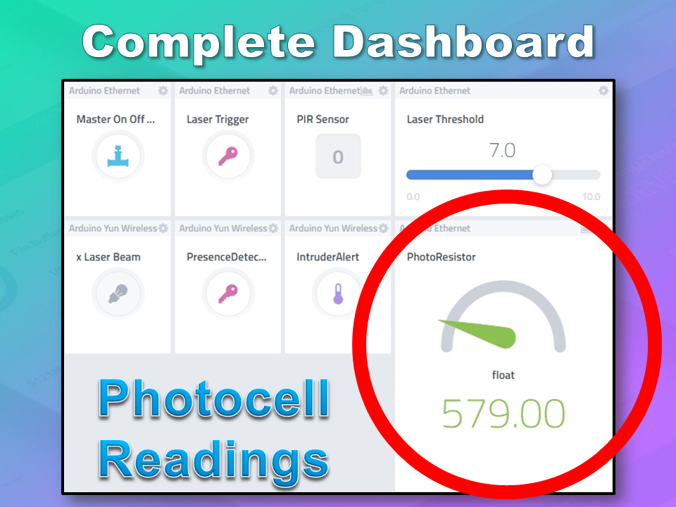
Arduino Ethernet - Photoresistor
This sensor will be used with the laser beam to create a laser tripwire. If the sensor detects a change in light levels (drops below the threshold), it will activate the laser trigger button on the dashboard. The person will then be required to identify themselves etc etc (similar to the motion detection by the PIR sensor). The photoresistor widget will display the raw analog reading from the sensor (connected to A2), but is associated with virtual channel 2. I used a virtual channel for more control over this sensor. To add the Photoresistor to the dashboard:
Add New
Device/Widget
Sensors
Luminosity
Photoresistor - Luminosity sensor
Widget Name: PhotoResistor
Select Device: Arduino Ethernet
Connectivity: Virtual
Pin: V2
Choose Widget: Value
Choose Icon: Light
Step2: Add Sensor
Arduino Ethernet - Laser Trigger
The laser trigger is just an indicator that someone tripped the laser beam. The state of this widget is used to notify the Seeeduino that a presence has been detected. This widget is associated with virtual pin 4 on the Arduino UNO with Ethernet.
Add New
Device/Widget
Actuators
Generic
Digital Output - Control a Digital Output
Widget Name: Laser Trigger
Select Device: Arduino Ethernet
Connectivity: Virtual
Pin: V4
Choose Widget: Button
Choose Icon: Lock
Step2: Add Actuator
Arduino Ethernet - Laser Threshold
The laser threshold is used to manually configure the light level at which the laser trigger will trip. When the photoresistor value drops below the threshold value, the laser trigger icon will activate. This allows the threshold value to be updated from the Cayenne dashboard, rather than having to manually adjust the value in the Arduino code. Also, this threshold can be set remotely, in that you don't have to be near the Arduino to change this value. A very useful feature of this Security system. This widget is associated with virtual pin 5 on the Arduino UNO with Ethernet.
Add New
Device/Widget
Actuators
Generic
PWM Output - Control a PWM Output
Widget Name: Laser Threshold
Select Device: Arduino Ethernet
Connectivity: Virtual
Pin: V5
Choose Widget: Slider
Slider Min Value: 0
Slider Max Value: 10
Step2: Add Actuator
The max value of the slider is 10 - due to a current bug in the Cayenne software. Once resolved, this value (as well as the relevant Arduino code) will need to be updated.
Seeeduino Cloud - Presence Detected
The presence detected widget is there to notify the Seeeduino Cloud that a presence has been detected on the Arduino Uno with Ethernet shield. When the PIR sensor detects movement or if the laser tripwire is tripped, Cayenne will change the state of the Presence Detected widget from LOW to HIGH. This is used within the Seeeduino Cloud to trigger the message "Place your keys on the Mat" . If a valid RFID tag is read by the Grove RFID reader, then this widget's state will change back from HIGH to LOW, and the MasterSwitch will be deactivated - turning the Security system off. This widget is associated with Virtual pin 6 on the Seeeduino Cloud.
Add New
Device/Widget
Actuators
Generic
Digital Output - Control a Digital Output
Widget Name: Presence Detected
Select Device: Seeeduino Cloud
Connectivity: Virtual
Pin: V6
Choose Widget: Button
Choose Icon: Lock
Step2: Add Actuator
Seeeduino Cloud - Intruder Alert
If a valid RFID tag is not read by the Grove RFID reader within 10 seconds of a presence detection event, an alarm will sound, and this widget will be activated. This will trigger a notification event - to notify me of the unauthorised intrusion - via SMS or email. I will also have a visual indicator on the Cayenne dashboard that an intrusion has taken place. This widget is associated with Virtual pin 7 on the Seeeduino Cloud.
Add New
Device/Widget
Actuators
Generic
Digital Output - Control a Digital Output
Widget Name: Laser Trigger
Select Device: Seeeduino Cloud
Connectivity: Virtual
Pin: V7
Choose Widget: Button
Choose Icon: Thermometer
Step2: Add Actuator
Seeeduino Cloud - Laser Beam
The laser beam widget was created to allow for full control over the laser beam. The laser beam can be turned on or off from the Cayenne dashboard, and a connected to digital pin 7 on the Seeeduino Cloud.
Add New
Device/Widget
Actuators
Light
Light Switch - Turn On/Off a Light
Widget Name: xLaser Beam
Select Device: Seeeduino Cloud
Connectivity: Digital
Pin: D7
Choose Widget: Button
Choose Icon: Light
Step2: Add Actuator
Cayenne Triggers
Now that all of the widgets have been added to the Dashboard, there is just one more step to complete the Security System. We need to setup the triggers. These triggers provide a level of automation that is easy to create within Cayenne, but would be very complicated otherwise. I set my triggers up as per the table below. Each row represents one of the triggers within my Cayenne dashboard. If you would like to see an example of how to add a trigger - please have a look at the video at the top of this tutorial.
Concluding comments
I used many different elements to put this home/office security project together - Multiple Arduinos were connected to the internet, both controlled by a web/smart phone app, cross-communication/synchronisation between the Arduinos, and the use of multiple sensors and modules including a laser beam !
This was way more than just a simple PIR sense and alarm project. I now have a personalised greeting and reminder system when I walk in the door. Everyone else has their own personalised greeting. I can enable my Security System remotely, from two blocks away, and if I wanted to - I could enable it from the other side of the world. I know instantly when someone has entered my house/office.... with an SMS alert straight to my phone.
This project could easily be extended:
Press a button on my phone to manually trigger/play a specific message/sound/song
Take a picture of the intruder
Introduce fire or leak detection aswell
Add other environmental sensors - Temperature / Humidity
Connect it to lamp/light - creating a security light
I am sure you can think of more things I could do with this system. In fact, why don't you mention your ideas in the comments below.
Cayenne was instrumental in getting this project to work. I don't think I would know where to start if I had to do this project without this cool IoT platform. I think I will definitely be trying out a few more projects using Cayenne, and should you want to do the same, then please make sure to join Cayenne Beta:
Here is the link you need to get to the right place: Cayenne Beta Link
If you like this page, please do me a favour and show your appreciation :
UPDATE: Magzor has just started a Kickstarter campaign. Please check it out to get a good package deal on many of their components. Many of which were used in this tutorial.
This tutorial will show you how to build your own Stroboscopic Animator using Magzor's Mechanotronic Design Portal as a starting point. Magzor Corporation is a business in California that is trying really hard to simplify robotic design. They want to enable users with little to no engineering experience to design and manufacture a custom robot by themselves in a matter of hours. What is a stroboscope? A stroboscope is an instrument that uses a strobe light to make a moving object look stationary… We will use this feature to create an interesting 4 picture animation on a rotating disk.
Have a look at the video below to see the project in action, and the MDP process walk-through:
Misc items: scrap paper, wood, brackets, screws, single and double-sided tape, cardboard.
Magzor Schematic Diagram
Click to zoom ...
Further build instructions can be obtained by selecting the components in the Mechanotronics Design Portal within the Magzor website. Generating the build, and then selecting "Setup Instructions" tab at the top of the page. See video above to see this process in action.
Arduino Sketch
Make sure to copy and paste the following code into your Arduino IDE. It doesn't seem to work directly from the browser. You also need to install the Arduino Magzor I2C library ( http://magzor.com/downloads/ )
Putting it together
Arduino MEGA
Magzor I2C board
MIC Boards
MIC Boards Assembled
Sensors, Modules and Shields - all put together
Motor with Bracket and Wire
Picture lined up with magnet on disk
Stroboscopic Animation
The Arduino MEGA microcontroller listens for the hall effect sensor to be triggered by the south facing side of the magnet on the underside of the rotating disk. As the magnet moves over the hall effect sensor, the sensor is triggered and the Arduino instructs the LED to blink for a fraction of a second. By manipulating the delay after the trigger time, we can get the LED to blink when one of the four images on the rotating disk is towards the front position. And if we get the timing right, we can make a simple animation.
If you watch the video above, you will see that the image bounces around a little bit. The duration of each frame is determined by the speed of the rotating disk (or motor), and the number of LED flashes per frame. Any changes in rotation speed will affect the position of the picture when the LED blinks. My rotating disk is not completely semetrical or centred correctly, and therefore a bit jumpy… but you get the idea. Bold images with high contrast seem to work best… Precision is key for this type of project. And if you can get the disk to rotate at a constant speed, you could probably do away with the hall effect sensors and magnets… however, in my case, these were essential in getting the project to work as intended.
This project is a lot of fun. You can really get creative by making your own pictures or 3 dimensional models (for a stop motion effect). Try different colours. It really is quite cool.
Concluding Comments
I would like to thank Magzor for supplying the components used in this tutorial, and letting me try out their MDP process. I really like the concept, the one stop shop which looks after you from beginning to end. Providing everything I needed to get the project off the ground. The point of this exercise was to go through the entire process of selecting the parts, build the project, and get it up and running. And I have done that in no time at all.
There is only one library to download and install, and the good thing is that you don't have to go hunting for it. The latest "correct" working version of the library is easy to find, right there on the Magzor website… Speaking of the Magzor website, please make sure to take a quick look around. It is quite impressive.
UPDATE: Magzor has just started a Kickstarter campaign. Please check it out to get a good package deal on many of their components. Many of which were used in this tutorial.
If you like this page, please do me a favour and show your appreciation :