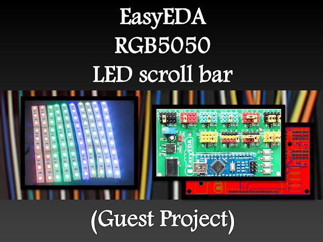
.
Hacking Robotic Arm using Controllino and Cayenne Reviewed by Unknown on 13:08 Rating: 4.5

Hacking Robotic Arm using Controllino and Cayenne


Description

This tutorial will show you how to take over the controls of the OWI Robotic Arm with the help of an Arduino compatible, open-source PLC called the Controllino MAXI, together with Cayenne (my go-to iOT application for remote connection to my Arduino projects). The Controllino MAXI will provide the physical connections to the OWI robotic arm, and Cayenne will allow me to control the arm via my web browser or via the Cayenne app on my phone.


Arduino Libraries and IDE

  1. The Arduino IDE can be used to program the Controllino. You can dowload the Arduino IDE from here: https://www.arduino.cc/en/main/software.
  2. You will also need to read the Cayenne Ethernet library installation instructions in order to install the Cayenne Ethernet Library.
  3. The Controllino will connect to the internet via the Ethernet port onboard.
  4. You do not need the Controllino library for this project, however, if you have a Controllino, you might as well install the library. You can read the Controllino library installation instructions from their GitHub webpage here: https://github.com/CONTROLLINO-PLC/CONTROLLINO_Library.
  5. You will need to notify the Arduino IDE of the Controllino MAXI board by pasting the supplied URL into the "Additional Boards Manager URLs" in the Arduino IDE.

  6. This is located under: FILE - PREFERENCES - Additional Boards Manager URLs.
  7. The URL that you need to paste is in STEP 3 of the Controllino Library installation instructions on their GitHub page.
  8. The video at the top of this tutorial may help clarify the process.


ARDUINO CODE:

The code above is very simple, however you will need to create a dashboard of widgets from within your Cayenne account in order to control the OWI robotic Arm from your phone or via the Dashboard webpage.


Setting up Cayenne Dashboard

Once you have created your Cayenne account, you will be presented with a webpage to choose a board to connect to. Controllino is an Arduino compatible PLC, so make sure to follow these instructions for setting up the Controllino in your Cayenne Account.

  1. Select Arduino from the available list of boards.
  2. Make sure to install the necessary libraries if your have not done so already.
  3. Select Arduino MEGA from the avaliable list of Arduino boards
  4. Select Ethernet Shield W5100
  5. Copy and paste the Arduino code that pops up on screen into your Arduino IDE and upload to the Controllino.
  6. Alternatively, copy and paste the code from above, however you will need to insert your Authentication token to get it to work

After you upload the code to the Controllino, and providing it has an ethernet cable connected to the internet router (and has access to the internet), and is powered on, it will connect to your Cayenne Dashboard. You can now add widgets to the dashboard in real time to interact with the Controllino, and without uploading any more code to the open source PLC.


Adding Widgets

We need to add a number of widgets in order to activate the relays on the Controllino. The relavent digital pins that we will need to know about can be found on the Controllino website here: https://controllino.biz/downloads/.

Here is the direct link to the PINOUT file for the Controllino MAXI.

"Armed" with that knowledge, we can now create the widgets which are necessary to control the relays on the Controllino. From within the Cayenne dashboard, please follow these instructions to create a widget:

  1. Select - ADD NEW
  2. Select - DEVICE/WIDGET
  3. Select - ACTUATORS
  4. Then - RELAY from the dropdown box
  5. Select - RELAY SWITCH
  6. Give the widget a descriptive name to differentiate it from the other widgets and a name that is somewhat informative (eg. R0 - Pos)
  7. I gave the first widget the name "R0 - Pos", because it will connect to Relay R0, and that relay will be connected to the Positive (POS) terminal of the OWI robotic arm.
  8. Select the device you would like to connect to. Be aware that you can change the name of the device in the settings. If you followed this tutorial, it should have the name "Arduino MEGA", but I changed the name of the device to "Controllino" to be more accurate.
  9. We will be using a digital pin to control the relay, therefore select "Digital" as the Connectivity option
  10. For this specific widget, we will be controlling R0, which is activated by digital pin D22 on the Controllino. Therefore select "D22" from the "Pin" dropdown box.
  11. Choose a "Button" as the widget type
  12. Choose an icon from the dropdown box that makes sense to you
  13. Skip Step 1
  14. Select Step 2: Add actuator

You should now see your new widget on the dashboard. Select the widget to enable or activate that relay. If you do this, and if everything goes to plan, you will see the LED for R0 illuminate on the Controllino. You now have to add the rest of the widgets to the dashboard in order to control the rest of the relays on the Controllino.


Widget Dashboard

Here is a table to show you how I setup my dashboard.


Fritzing diagram


OWI Robotic Arm Pins


Normal OWI Robotic Arm Circuit

The following circuit diagram will show you how the wired control box is normally connected to the OWI Robotic arm. This is the circuit diagram of the OWI robotic arm under normal operating contidtions.


OWI Robotic Arm Circuit when connected to Controllino

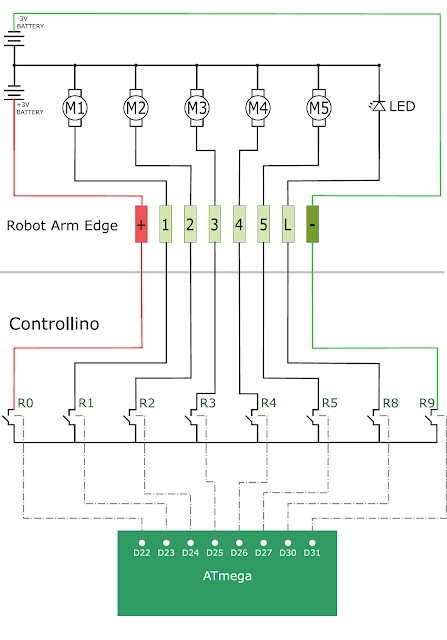
The following circuit diagram will show you how the OWI Robotic Arm will be controlled by the relays of the Controllino. This is the circuit diagram of the OWI robotic arm when it is connected to the Controllino.


All connected

The OWI Robotic Arm is connected to a breadboard using the female-to-male jumper wires. Solid core wire is then fed through to the relay terminals of the Controllino. You could just wire it up so that the robotic arm is connected directly to the Controllino, however, I did not have the right connectors for this purpose.
The Controllino is also connected to my internet router via a normal RJ-45 ethernet cable, and is powered by a 12V DC power adapter.


Summary

Now that you have all the physical connections made, uploaded the code to the Controllino, and have created your dashboard in Cayenne, you should be able to control your OWI Robotic arm from anywhere in the world. As demonstrated in the video at the start of this tutorial, the robotic arm has quite a bit of give on each of the joints, which makes it difficult to achieve certain tasks that require an element of precision. There goes that idea of being able to perform surgery with this thing !!! At least you can get it to make you a cup of tea, and if you are patient enough, you might even get a grape once in a while.

Thank you to Controllino and Cayenne for making this tutorial possible. If you would like your product featured in my tutorials, please contact me on my contact page.


If you like this page, please do me a favour and show your appreciation :

 
Visit my ArduinoBasics Google + page.
Follow me on Twitter by looking for ScottC @ArduinoBasics.
I can also be found on Pinterest and Instagram.
Have a look at my videos on my YouTube channel.

Description: Hacking Robotic Arm using Controllino and Cayenne Rating: 3.5 Reviewer: Unknown ItemReviewed: Hacking Robotic Arm using Controllino and Cayenne
HMC5883L on the GY-80 module Reviewed by Unknown on 23:20 Rating: 4.5

HMC5883L on the GY-80 module

Description

In this tutorial, I will show you how to configure and extract data from the magnetometer (HMC5883L) sensor on the GY-80 10DOF module from ICStation. While there are some very good libraries on the internet which will give you full access to this sensor, I will show you what you need to know without using a library. This means that it may get a bit technical at times, but I will hold your hand along the way and provide explanations as required. I would also recommend that you watch the complete video from start to finish - as the video provides really useful information.


HMC5883L Magnetometer Datasheet:

You can find the datasheet for the HMC5883L pretty easily by searching on the internet. Here are a couple of sources:


Arduino Libraries

This tutorial does not use any external libraries.
It does use the Wire library for I2C communication.
However, there is no extra download required to access the Wire library.
If you are looking for a library specific for the HMC5883L sensor, then I would recommend one of these:

Like I said - you do not need an HMC5883L library for this tutorial. The libraries above are listed for those who wish to learn more about this particular sensor.

Arduino IDE

The Arduino IDE can be downloaded from the Arduino website. Visit the Arduino IDE download page.

I generally use the ZIP file for Windows and never seem to have any issues.
There are downloads available for all the major operating systems.


ARDUINO CODE:

I have created a Gist for the Arduino code to configure and extract data from the HMC5883L sensor. However, I also have a GitHub repository which aims to capture the code for all of the sensors on the GY-80 module. Code for the other sensors will become available in due time. Meanwhile, have a look at the code below for the HMC5883L sensor:

This code will set all axis values to 1000 upon startup. Moving the GY-80 module around will result in a value greater or less than 1000, however, returning the sensor back to it's original position, should result in values very close to 1000 on each axis. I chose to introduce this calibration in order to avoid negative values, and I liked the fact that I could set a heading with values that were easy to remember.
 
The magSetting function was created to easily configure the magnetometer.
Make sure to look at the video and also the datasheet for further information about calibrating the magnetometer.
 
The getReadings function was created to easily retrieve the magnetometer axis data. I chose to use Single measurement mode in this tutorial.


Hooking it up:

You can communicate with any of the sensors on the GY-80 module using I2C. The HMC5883L magnetometer sensor is no different. You will need four connections between the Arduino UNO and the GY-80 module. Have a look at the diagram below for the connection diagram and table.

Fritzing diagram


Project pictures


Concluding comments

The HMC5883L sensor on the GY-80 module is quite interesting and works relatively well. There are a number of other sensors on the GY-80 module which can provide complementary positional data. At some point, I plan to come back and explain some of the other sensors on this module, but first I would like to create a real-life project using the magnetometer. So stay tuned. You may want to subscribe to my social networks or to this blog to be notified of that project when I complete it.

I would like to thank ICStation for their collaborative efforts. Their contribution was invaluable to this tutorial's existence.

If you like this page, please do me a favour and show your appreciation :

 
Visit my ArduinoBasics Google + page.
Follow me on Twitter by looking for ScottC @ArduinoBasics.
I can also be found on Pinterest and Instagram.
Have a look at my videos on my YouTube channel.

Description: HMC5883L on the GY-80 module Rating: 3.5 Reviewer: Unknown ItemReviewed: HMC5883L on the GY-80 module
EasyEDA RGB5050 LED Scroll Bar Reviewed by Unknown on 13:09 Rating: 4.5

EasyEDA RGB5050 LED Scroll Bar


Guest Post Disclaimer

This is a guest post by the EasyEDA team. I would like to thank EasyEDA for providing this tutorial for everyone to enjoy. All information within this post was provided by EasyEDA.


Description

None of us could deny the fact that we would love with to play with LED’s and lighting stuff. I love to play with LED’s and create attractive lighting effects. This project was a result of such an attempt where I created a stunning RGB light effect using the popular development platform Arduino Nano. Let’s see the circuit, code and instruction on building this project:


Image source: EasyEDA


Arduino Libraries and IDE

No libraries are required for this project. The Arduino IDE can be downloaded from the Arduino website. Here is the download link.

ARDUINO CODE:


Preparing the LED strips

Cut down the LED strips into 10 single pieces. Make sure you cut them into equal halves and make sure that only the copper conduction plate in the strip is cut. Making a wrong cut disrupts the electrical conductivity between the LED’s. After cutting down into separate strips, you will need to connect each strip using a Dupont wire connectors.

Image source: EasyEDA


Designing the Control Board

I have made a custom control board that incorporates an Arduino Nano. The control board is used to boost the incoming signal from Arduino and lights up the corresponding LED strips.


Image source: EasyEDA


Control Board Circuit diagram

I used a free Online circuit and PCB designing platform called EasyEDA to develop my control board. It is pretty easy to use especially because of the large library of parts to choose from. Once the design is complete, you have the option to order it through EasyEDA. They offers great prices on custom PCB manufacturing. I have added 10 connection points for 10 LED strips. Each RGB LED strip is controlled by one of the Arduino Nano digital pins.. Transistors Q1,Q2,Q3….Q10 act as a switch for these LED strips for controlling 12V strips via a 5V signal from the Arduino. And switches S1,S2..S4 were added to be able to select the effect on the strip. The schematic can be seen below:


Schematic

You can access the actual EasyEDA schematic by clicking on the image below:

Image source: EasyEDA


PCB Board Design

Here is the PCB board design for this project.
You can access the actual EasyEDA design by clicking on the image below.

Image source: EasyEDA


PCB Fabrication

After completing the PCB design, you can click on the Fabrication icon.

You will then have access to the PCB order page which will allow you to download your PCB Gerber files that can be sent to any manufacturer. However it is a lot easier (and cheaper) to order it directly from EasyEDA.
Here you can select:

  • the number of PCBs you want to order
  • the number of copper layers you need
  • the PCB thickness
  • copper weight
  • and even the PCB color
After you’ve selected all of the options, click “Save to Cart” and complete you order. You will then get your PCBs shipped a few days later.

Image source: EasyEDA


PCB final product

When I received the PCBs, I am quite impressed with the quality, they are pretty nice.

Image source: EasyEDA


PCB Build of Materials

Image source: EasyEDA


PCB connections

Connect the LED strips through the connection points in the board. Make sure that you connect these correctly (push the connectors all the way onto the pin), because the chances of a short increase significantly with the number of wires connected. Once all the connections are done all that left is to install your Arduino Nano (pre-programmed with the Arduino code above), and to power the PCB with a 12V power supply.


Image source: EasyEDA


Project Video


Concluding comments

Hope you like this RGB light effects project, do try it out and post your feedback below.
 
Disclaimer:
This is a guest blog post by the EasyEDA team. All information within this post was provided by EasyEDA.

Description: EasyEDA RGB5050 LED Scroll Bar Rating: 3.5 Reviewer: Unknown ItemReviewed: EasyEDA RGB5050 LED Scroll Bar
Arduino based Security Project Using Cayenne Reviewed by Unknown on 11:11 Rating: 4.5

Arduino based Security Project Using Cayenne


Description

This is an Arduino based home security project that uses the power of "Cayenne" for extraordinary capabilities.

Cayenne Beta

Cayenne is a new IoT drag and drop platform originally released for the Raspberry Pi, but now available for Arduino. Cayenne makes the task of connecting your Arduino to the internet as simple as possible. All of the complexity of internet connectivity is hidden within the Cayenne library.

You can easily create a Network of Arduinos and build an IoT system which can be managed and operated within the Cayenne dashboard. This dashboard is accessible through your browser or via the Cayenne smart phone app (on IOS or Android).

The feature I liked the most, was the ability to change the position of sensors or actuators on the Arduino without having to re-upload Arduino code. I could manage the changed position from within the Cayenne platform. The other feature that I liked was the ability to setup actions based on custom triggers. You can use Cayenne to trigger a whole range of functions, for example: play a sound, move a motor, light up an LED, or to send alert notifications via email or SMS.

Cayenne is in Beta at the moment, so there are a few minor bugs here and there, but overall - I give it a thumbs up - it is definitely worth checking out.
 

Here is a link to the Cayenne Beta Program:
**Cayenne Beta Link**


              Source: myDevices Media Kit


Home Security Project Summary

In order to fully experience this new IoT platform, I decided to create a project to really put it through its paces. This is what my Security Project will need:

  1. It will use two Arduinos, one connected to the internet via an Ethernet shield, and the other via WIFI.
  2. Two detectors - a PIR sensor and a laser trip wire.
  3. If the sensors are tripped, the person has 10 seconds to present an RFID tag to the Grove RFID reader:
    • If a valid RFID tag is SUCCESSFULLY presented within the time limit, a nice personalised greeting will be played to that person using a Grove - Serial MP3 player
    • If a valid RFID FAILS to be presented within the time limit, an Alarm will sound, and I will be notified of the intrusion via an SMS alert.
  4. The Cayenne dashboard will show the status of the sensors, and I will have full control over my security system via the web interface (or smartphone app).
  5. The sensors will be attached to a different Arduino to that of the Grove MP3 player and the RFID tag reader, which means that there will have to be some level of communication between the two Arduinos. In fact, the cross communication will be vital to the success of this project.


Project Video


Flow Diagrams:

Main Flow Diagram

The following flow diagram shows the Security project process. It is a high level view of the decisions being made by each Arduino in response to various events.  


Triggers Flow Diagram

The following flow diagram aims to highlight the various triggers set up within Cayenne to get this Security system to work.  


Arduino IDE and Library Downloads

You will need an Arduino IDE to upload code to the Arduino and the Seeeduino Cloud.
Here is the link to the Arduino IDE: Arduino IDE - download location

The Cayenne service requires that you download and install the Cayenne Library into your Arduino IDE.
You can get the Cayenne Library from here: Cayenne Library File - Download


Cayenne Connectivity Setup

The Seeeduino Cloud needs to be prepared for use with Cayenne.
Normal operating/setup instructions can be found here: Seeeduino Cloud WIKI page
 
Once you have successfully connected Seeeduino Cloud to your WIFI network, you can add it to the Cayenne Dashboard by making the following selections from within the Cayenne Web application:

  1. Add New
  2. Device/Widget
  3. Microcontrollers
  4. Arduino
  5. Ensure Seeeduino Cloud is connected to WIFI network - the select the NEXT button
  6. Select - Arduino Yun: Built-in Ethernet - ticked
  7. Providing you have already installed the Cayenne library as described above - you should be able to copy and paste the code to the Arduino IDE and upload to the Seeeduino Cloud.
  8. If successful, you should see the Arduino Yun board appear within the Cayenne Dashboard. If not, then seek help within the Cayenne forum.


The Arduino UNO with WIZNET 5100 - Ethernet Shield
also needs to be prepared with Cayenne

  1. Add New
  2. Device/Widget
  3. Microcontrollers
  4. Arduino
  5. Ensure Arduino is powered, and Ethernet shield is connected to your internet router via an Ethernet cable
  6. Select - Arduino Uno: Ethernet Shield W5100 - ticked
  7. Copy and paste the code to the Arduino IDE and upload to the Arduino UNO.
  8. If successful, you should see the Arduino Uno board appear within the Cayenne Dashboard. If not, then seek help within the Cayenne forum.


If you have the Ethernet shield with the WIZNET 5200 chip, then you may need to download a specific Ethernet library in addition to the Cayenne library.
 
Just follow the instructions within the Automatically generated sketch provided - when you select your specific Arduino/Ethernet/WIFI shield combination. If you need further instructions on connecting your device to Cayenne - then please visit the myDevices website for the online documentation.


ARDUINO CODE (1)


Code for Arduino UNO with Ethernet Shield:

The following code will need to be uploaded to the Arduino UNO:


ARDUINO CODE (2)


Code for Seeeduino Cloud:

The following code will need to be uploaded to the Seeeduino Cloud:


Fritzing diagram (1)


Fritzing diagram for Arduino UNO with Ethernet

Please click on the picture below for an enlarged version of this fritzing diagram


Fritzing diagram (2)


Fritzing diagram for Seeeduino Cloud

Please click on the picture below for an enlarged version of this fritzing diagram


Cayenne Dashboard Setup - GUI


The Arduino code only provides half of the functionality of this project. The Cayenne Dashboard needs to be setup to provide the rest of the functionality. The following instructions will show you how to add each of the widgets required for this Home Security project.


Arduino Ethernet - Master Switch

The master switch allows me to turn the security system on and off. When I turn the MASTER SWITCH ON, the laser beam will turn on, and the sensors will start monitoring the area for intruders. This widget is NOT associated with a physical switch/sensor on the Arduino - it uses virtual channel 0. We need to add the Master switch to the dashboard:


  1. Add New
  2. Device/Widget
  3. Actuators
  4. Generic
  5. Digital Output - Control a Digital Output
  6. Widget Name: Master On Off Switch
  7. Select Device: Arduino Ethernet
  8. Connectivity: Virtual
  9. Pin: V0
  10. Choose Widget: Button
  11. Choose Icon: Valve
  12. Step2: Add Actuator
We will add a trigger later to get this button to automatically turn the Laser beam on.


Arduino Ethernet - PIR Sensor

This sensor will be used to detect movement in the room. If a person walks into the room, this sensor will detect movement, and will trigger a message to be played on the Grove Serial MP3 player. The message will aim to get the person to identify themselves. They identify themselves by placing their RFID tag in close proximity to the Grove RFID reader. If the tag is valid, a "Welcome home" message is played on the Grove MP3 player. If a valid tag is not presented to the reader within 10 seconds, an Alarm will go off ("Alarm sound" played on Grove MP3 player.)

The PIR sensor is connected to digital Pin 6 of the Arduino, however, it is mapped to virtual pin 1 for better synchronisation with the Cayenne dashboard. This was done to capture ALL detections - as the PIR sensor could change from a LOW to HIGH and back to LOW state in between a Cayenne state check - and therefore, Cayenne could miss this motion detection.. Therefore we need to assign the PIR sensor to a virtual channel in the following way:
  1. Add New
  2. Device/Widget
  3. Sensors
  4. Motion
  5. Digital Motion Sensor - Motion Detector
  6. Widget Name: PIR sensor
  7. Select Device: Arduino Ethernet
  8. Connectivity: Virtual
  9. Pin: V1
  10. Choose Widget: 2-State Display
  11. Choose Icon: Light
  12. Step2: Add Sensor
  13. Select Settings from the PhotoResistor
  14. Choose Display: Value
  15. Save


Arduino Ethernet - Photoresistor

This sensor will be used with the laser beam to create a laser tripwire. If the sensor detects a change in light levels (drops below the threshold), it will activate the laser trigger button on the dashboard. The person will then be required to identify themselves etc etc (similar to the motion detection by the PIR sensor). The photoresistor widget will display the raw analog reading from the sensor (connected to A2), but is associated with virtual channel 2. I used a virtual channel for more control over this sensor. To add the Photoresistor to the dashboard:

  1. Add New
  2. Device/Widget
  3. Sensors
  4. Luminosity
  5. Photoresistor - Luminosity sensor
  6. Widget Name: PhotoResistor
  7. Select Device: Arduino Ethernet
  8. Connectivity: Virtual
  9. Pin: V2
  10. Choose Widget: Value
  11. Choose Icon: Light
  12. Step2: Add Sensor


Arduino Ethernet - Laser Trigger

The laser trigger is just an indicator that someone tripped the laser beam. The state of this widget is used to notify the Seeeduino that a presence has been detected. This widget is associated with virtual pin 4 on the Arduino UNO with Ethernet.

  1. Add New
  2. Device/Widget
  3. Actuators
  4. Generic
  5. Digital Output - Control a Digital Output
  6. Widget Name: Laser Trigger
  7. Select Device: Arduino Ethernet
  8. Connectivity: Virtual
  9. Pin: V4
  10. Choose Widget: Button
  11. Choose Icon: Lock
  12. Step2: Add Actuator


Arduino Ethernet - Laser Threshold

The laser threshold is used to manually configure the light level at which the laser trigger will trip. When the photoresistor value drops below the threshold value, the laser trigger icon will activate. This allows the threshold value to be updated from the Cayenne dashboard, rather than having to manually adjust the value in the Arduino code. Also, this threshold can be set remotely, in that you don't have to be near the Arduino to change this value. A very useful feature of this Security system. This widget is associated with virtual pin 5 on the Arduino UNO with Ethernet.

  1. Add New
  2. Device/Widget
  3. Actuators
  4. Generic
  5. PWM Output - Control a PWM Output
  6. Widget Name: Laser Threshold
  7. Select Device: Arduino Ethernet
  8. Connectivity: Virtual
  9. Pin: V5
  10. Choose Widget: Slider
  11. Slider Min Value: 0
  12. Slider Max Value: 10
  13. Step2: Add Actuator
The max value of the slider is 10 - due to a current bug in the Cayenne software. Once resolved, this value (as well as the relevant Arduino code) will need to be updated.


Seeeduino Cloud - Presence Detected

The presence detected widget is there to notify the Seeeduino Cloud that a presence has been detected on the Arduino Uno with Ethernet shield. When the PIR sensor detects movement or if the laser tripwire is tripped, Cayenne will change the state of the Presence Detected widget from LOW to HIGH. This is used within the Seeeduino Cloud to trigger the message "Place your keys on the Mat"
. If a valid RFID tag is read by the Grove RFID reader, then this widget's state will change back from HIGH to LOW, and the MasterSwitch will be deactivated - turning the Security system off. This widget is associated with Virtual pin 6 on the Seeeduino Cloud.

  1. Add New
  2. Device/Widget
  3. Actuators
  4. Generic
  5. Digital Output - Control a Digital Output
  6. Widget Name: Presence Detected
  7. Select Device: Seeeduino Cloud
  8. Connectivity: Virtual
  9. Pin: V6
  10. Choose Widget: Button
  11. Choose Icon: Lock
  12. Step2: Add Actuator


Seeeduino Cloud - Intruder Alert

If a valid RFID tag is not read by the Grove RFID reader within 10 seconds of a presence detection event, an alarm will sound, and this widget will be activated. This will trigger a notification event - to notify me of the unauthorised intrusion - via SMS or email. I will also have a visual indicator on the Cayenne dashboard that an intrusion has taken place. This widget is associated with Virtual pin 7 on the Seeeduino Cloud.

  1. Add New
  2. Device/Widget
  3. Actuators
  4. Generic
  5. Digital Output - Control a Digital Output
  6. Widget Name: Laser Trigger
  7. Select Device: Seeeduino Cloud
  8. Connectivity: Virtual
  9. Pin: V7
  10. Choose Widget: Button
  11. Choose Icon: Thermometer
  12. Step2: Add Actuator


Seeeduino Cloud - Laser Beam

The laser beam widget was created to allow for full control over the laser beam. The laser beam can be turned on or off from the Cayenne dashboard, and a connected to digital pin 7 on the Seeeduino Cloud.


  1. Add New
  2. Device/Widget
  3. Actuators
  4. Light
  5. Light Switch - Turn On/Off a Light
  6. Widget Name: xLaser Beam
  7. Select Device: Seeeduino Cloud
  8. Connectivity: Digital
  9. Pin: D7
  10. Choose Widget: Button
  11. Choose Icon: Light
  12. Step2: Add Actuator


Cayenne Triggers

Now that all of the widgets have been added to the Dashboard, there is just one more step to complete the Security System. We need to setup the triggers. These triggers provide a level of automation that is easy to create within Cayenne, but would be very complicated otherwise. I set my triggers up as per the table below. Each row represents one of the triggers within my Cayenne dashboard. If you would like to see an example of how to add a trigger - please have a look at the video at the top of this tutorial.  


Concluding comments

I used many different elements to put this home/office security project together - Multiple Arduinos were connected to the internet, both controlled by a web/smart phone app, cross-communication/synchronisation between the Arduinos, and the use of multiple sensors and modules including a laser beam !
 
This was way more than just a simple PIR sense and alarm project. I now have a personalised greeting and reminder system when I walk in the door. Everyone else has their own personalised greeting. I can enable my Security System remotely, from two blocks away, and if I wanted to - I could enable it from the other side of the world. I know instantly when someone has entered my house/office.... with an SMS alert straight to my phone.
 
This project could easily be extended:

  1. Press a button on my phone to manually trigger/play a specific message/sound/song
  2. Take a picture of the intruder
  3. Introduce fire or leak detection aswell
  4. Add other environmental sensors - Temperature / Humidity
  5. Connect it to lamp/light - creating a security light
I am sure you can think of more things I could do with this system. In fact, why don't you mention your ideas in the comments below.
 
Cayenne was instrumental in getting this project to work. I don't think I would know where to start if I had to do this project without this cool IoT platform. I think I will definitely be trying out a few more projects using Cayenne, and should you want to do the same, then please make sure to join Cayenne Beta:
 
Here is the link you need to get to the right place: Cayenne Beta Link


If you like this page, please do me a favour and show your appreciation :

 
Visit my ArduinoBasics Google + page.
Follow me on Twitter by looking for ScottC @ArduinoBasics.
I can also be found on Pinterest and Instagram.
Have a look at my videos on my YouTube channel.

Description: Arduino based Security Project Using Cayenne Rating: 3.5 Reviewer: Unknown ItemReviewed: Arduino based Security Project Using Cayenne
Back to top