.
Prextron CHAIN BLOCKS - Arduino Nano controlled Ultrasonic sensor that switches a motor wirelessly using 433MHz RF modules and a relay board. Reviewed by Unknown on 09:01 Rating: 4.5

Prextron CHAIN BLOCKS - Arduino Nano controlled Ultrasonic sensor that switches a motor wirelessly using 433MHz RF modules and a relay board.


Description

In this tutorial, I will be evaluating Prextron CHAIN blocks – a new system that allows you to connect your sensors and actuators to an Arduino NANO using clever 3D-printed prototyping boards that can be stacked sideways. This very modular system makes it easy to connect, disconnect and replace project components, and eliminate the “rats nest of wires” common to many advanced Arduino projects. CHAIN BLOCKS are open, which means that you can incorporate any of your sensors or actuators to these prototyping boards, and you can decide which specific pin on Arduino you plan to use. The CHAIN BLOCK connections prevent or reduce common connection mistakes, which make them ideal for class-room projects and learning activities.

I am going to set up a project to put these CHAIN BLOCKs to the test:
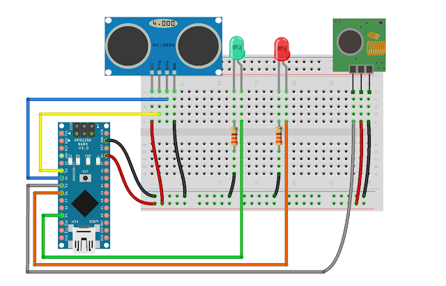
When I place my hand in-front of an Ultrasonic sensor, the Arduino will transmit a signal wirelessly to another Arduino, and consequently turn on a motor.


Parts Required:

You need the following Prextron Chain Blocks


Please note: You may need to solder the module wires to the CHAIN BLOCK protoboard.


Arduino Libraries and IDE

This project does not use any libraries. However, you will need to upload Arduino code to the Arduino. For this you will need the Arduino IDE which can be obtained from the official Arduino website:
https://www.arduino.cc/en/main/software


ARDUINO CODE: RF Transmitter


ARDUINO CODE: RF Receiver


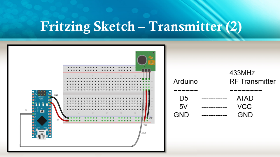
Fritzing diagrams for Transmitter


Fritzing diagrams for Receiver


Concluding comments

The purpose of this project was to evaluate Prextron CHAIN BLOCKs and put them to the test. Here is what I thought of CHAIN BLOCKS at the time of evaluation. Some of my points mentioned below may no longer apply to the current product. It may have evolved / improved since then. So please take that into consideration


What I liked about Chain Blocks

  • The design is simple, the product is simple.
  • Once the Chain Blocks were all assembled, they were very easy to connect to each other.
  • I can really see the benefit of Chain Blocks in a teaching environment, because it simplifies the connection process, and reduces connection mixups.
  • It was good to see that the blocks come in different colours, which means that you can set up different colour schemes for different types of modules.
  • You can incorporate pretty much any sensor or Actuator into the Chain block which is very appealing.
  • You also have the flexibility of choosing which pins you plan to use on the Arduino.
  • Projects look a lot neater, because you no longer have the rats nest of wires.
  • The Blocks lock into each other which means that they are much easier to transport/carry.


What I did not like about Chain Blocks

  • In most cases, the Chain Block protoboard lanes were not numbered, which increased the chances of making mistakes when soldering
  • The need to solder modules to the protoboard, may be a discouragement for some people.
  • I would have liked a choice of different size Chain blocks. Some of the sensors did not fit nicely into the Square blocks.
  • Prextron really need to work on their website if they plan to get serious with this product: Webpage has incomplete functionality or irrelevant links etc etc.


Thank you very much to Prextron for providing the CHAIN BLOCKS used in this tutorial, and allowing me to try out their product. If you are interested in trying them yourself, then make sure to visit them at:


If you like this page, please do me a favour and show your appreciation :

 
Visit my ArduinoBasics Google + page.
Follow me on Twitter by looking for ScottC @ArduinoBasics.
I can also be found on Pinterest and Instagram.
Have a look at my videos on my YouTube channel.

Description: Prextron CHAIN BLOCKS - Arduino Nano controlled Ultrasonic sensor that switches a motor wirelessly using 433MHz RF modules and a relay board. Rating: 3.5 Reviewer: Unknown ItemReviewed: Prextron CHAIN BLOCKS - Arduino Nano controlled Ultrasonic sensor that switches a motor wirelessly using 433MHz RF modules and a relay board.
EasyEDA RGB5050 LED Scroll Bar Reviewed by Unknown on 13:09 Rating: 4.5

EasyEDA RGB5050 LED Scroll Bar


Guest Post Disclaimer

This is a guest post by the EasyEDA team. I would like to thank EasyEDA for providing this tutorial for everyone to enjoy. All information within this post was provided by EasyEDA.


Description

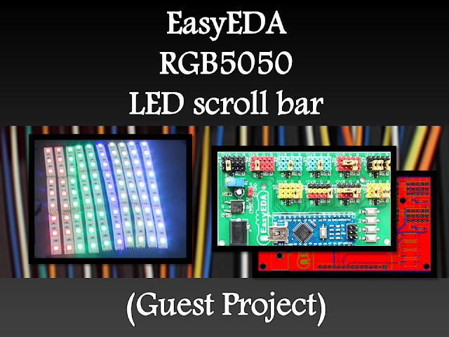
None of us could deny the fact that we would love with to play with LED’s and lighting stuff. I love to play with LED’s and create attractive lighting effects. This project was a result of such an attempt where I created a stunning RGB light effect using the popular development platform Arduino Nano. Let’s see the circuit, code and instruction on building this project:


Image source: EasyEDA


Arduino Libraries and IDE

No libraries are required for this project. The Arduino IDE can be downloaded from the Arduino website. Here is the download link.

ARDUINO CODE:


Preparing the LED strips

Cut down the LED strips into 10 single pieces. Make sure you cut them into equal halves and make sure that only the copper conduction plate in the strip is cut. Making a wrong cut disrupts the electrical conductivity between the LED’s. After cutting down into separate strips, you will need to connect each strip using a Dupont wire connectors.

Image source: EasyEDA


Designing the Control Board

I have made a custom control board that incorporates an Arduino Nano. The control board is used to boost the incoming signal from Arduino and lights up the corresponding LED strips.


Image source: EasyEDA


Control Board Circuit diagram

I used a free Online circuit and PCB designing platform called EasyEDA to develop my control board. It is pretty easy to use especially because of the large library of parts to choose from. Once the design is complete, you have the option to order it through EasyEDA. They offers great prices on custom PCB manufacturing. I have added 10 connection points for 10 LED strips. Each RGB LED strip is controlled by one of the Arduino Nano digital pins.. Transistors Q1,Q2,Q3….Q10 act as a switch for these LED strips for controlling 12V strips via a 5V signal from the Arduino. And switches S1,S2..S4 were added to be able to select the effect on the strip. The schematic can be seen below:


Schematic

You can access the actual EasyEDA schematic by clicking on the image below:

Image source: EasyEDA


PCB Board Design

Here is the PCB board design for this project.
You can access the actual EasyEDA design by clicking on the image below.

Image source: EasyEDA


PCB Fabrication

After completing the PCB design, you can click on the Fabrication icon.

You will then have access to the PCB order page which will allow you to download your PCB Gerber files that can be sent to any manufacturer. However it is a lot easier (and cheaper) to order it directly from EasyEDA.
Here you can select:

  • the number of PCBs you want to order
  • the number of copper layers you need
  • the PCB thickness
  • copper weight
  • and even the PCB color
After you’ve selected all of the options, click “Save to Cart” and complete you order. You will then get your PCBs shipped a few days later.

Image source: EasyEDA


PCB final product

When I received the PCBs, I am quite impressed with the quality, they are pretty nice.

Image source: EasyEDA


PCB Build of Materials

Image source: EasyEDA


PCB connections

Connect the LED strips through the connection points in the board. Make sure that you connect these correctly (push the connectors all the way onto the pin), because the chances of a short increase significantly with the number of wires connected. Once all the connections are done all that left is to install your Arduino Nano (pre-programmed with the Arduino code above), and to power the PCB with a 12V power supply.


Image source: EasyEDA


Project Video


Concluding comments

Hope you like this RGB light effects project, do try it out and post your feedback below.
 
Disclaimer:
This is a guest blog post by the EasyEDA team. All information within this post was provided by EasyEDA.

Description: EasyEDA RGB5050 LED Scroll Bar Rating: 3.5 Reviewer: Unknown ItemReviewed: EasyEDA RGB5050 LED Scroll Bar
Arduino Disco Ball Cake Reviewed by Unknown on 13:38 Rating: 4.5

Arduino Disco Ball Cake


Description

This is a fun project that will surely impress anyone you make this for. If you are having a "Disco" themed party, you cannot have a boring old cake. Let me tell you, this is probably the only Arduino project that my wife has ever been willing to be a part of. She did the hard work of putting the cake together, and I, well.... I was in charge of lighting. My biggest fear was that one of the wires would come loose and ruin the event at the most critical moment... While a wire did come loose, I managed to fix it in time before the guests arrived. Ok enough of my monologue, let me show you how to make one of these things.


Parts Required:


Arduino Libraries and IDE

You can get the Arduino IDE from here: https://www.arduino.cc/en/Main/Software
I used version 1.6.4, which is probably way out of date... but works fine nonetheless.
 
You can get information about how to use the FastLED library here: http://fastled.io/
And you can download it from here: FastLED Library
I used version 3.0.3, which is also probably out of date.

ARDUINO CODE:

ARDUINO CODE DESCRIPTION:

  • FastLED Library: You need to make sure that you have downloaded and installed the FastLED library into your Arduino IDE. The library is included in this sketch otherwise the FastLED functions will not work.
  • The "NUM_LEDS" variable: tells the Arduino how many LEDS are in use. In this case, we have 4 LED rings, with each LED ring containing 16 LEDs, and therefore a total of 64 LEDs. If you define a lower number, for example 16, then the sketch would only illuminate the LEDs on the first LED ring.
  • The "DATA_PIN" variable: tells the Arduino which Digital Pin to use for data transmission to the LED ring. In this case, I am using Digital Pin 9.
  • Other variables: I have a couple of other variables which are used for LED randomisation and hue control. Hue is the colour of the LED. By incrementing the hue variable, you can get the LEDs to cycle in a rainbow-like pattern. The "hue" variable is a "byte", which means that it will only go up to a maximum value of 255, before it jumps back down to zero.
  • Initialisation Code: If you have a different LED ring to the one in this tutorial, you may have to modify the initialisation code. This LED ring has a WS2812-B chipset (according to the ICStation website), and so this line:
     
    FastLED.addLeds(leds, NUM_LEDS); Will tell the FastLED library which chipset is being used (NEOPIXEL), the pin used for data transmission (DATA_PIN), the LED array to be controlled (leds), and the number of LEDs to be controlled (NUM_LEDS).
  • In the "loop()": section of the code: the "hue" variable is incremented to create a rainbow effect, and a random LED is selected using the FastLED's random8() function.
  • The random8(x) function: will randomly choose a number from 0 to x.
  • The randomSeed() function: is there to help "truely randomise" the number. This is helped by reading the randomness of a floating analogPin (A0). It doesn't have to be analogPin 0, it can be any unused analog pin.
  • leds[rnd].setHSV(hue,255,255): This line sets the random LED to have a hue equal to the "hue" variable, saturation equal to 255, and brightness equal to 255. Saturation equal to zero will make the LED shine white.
    Brightness of zero essentially turns the LED OFF.
  • FastLED.show(): No physical changes will be made to the LED ring display until a message is sent from the Arduino to the Digital input pin of the LED ring. This message is transmitted when you call the FastLED.show(); function. This tells the LED rings to update their display with the information contained within the led array (leds). So if you set all LEDs to turn on, the board will not illuminate the LEDs until the FastLED.show(); function is called. This is important to know - especially when trying to design your own LED sequences.
  • The delay(50) line: will set the amount of time between flashes to 50 milliseconds. You can change the delay to increase or decrease the number of flashes per second.
  • The leds[i].fadeToBlackBy( 180 ) function: essentially fades the LEDS by 180 units. You can increase or decrease this number to achieve the desired fade speed. Be warned however, that if you forget to call this function or if you fail to fade the LEDs sufficiently, then you may end up with ALL LEDs turning on, which could potentially destroy your Arduino board - i.e. depending on the number of LED rings you have, and how you have chosen to power them.


The Cake


  • Slide 1 - Base Plate: It is important to create the base plate with all of the electronics fitted and in working order BEFORE you put the Cake onto it. Trying to fit wires/cables LEDs and circuits under the base plate while there is a Cake ontop is a recipe for disaster. So prepare the base plate first, and then move to the cake making part later.
  • Slide 2 - Bake Cake: You will need a couple of hemisphere cake pans to make the two sides of the ball. You have to make a relatively dense cake to withstand the overall weight of the cake, icing and fondant, and to maintain it's shape. Once cooled and chilled, you can place them ontop of each other to form a sphere. They are held together by a layer of icing between them.
  • Slide 3 - Fondant Icing: The fondant icing has to be rolled out on a special non-stick mat. We found that adding a bit of flour helped to reduce the stickiness. There are special rollers which ensure that the thickness of the fondant is consistent throughout. You then have to cut them into square pieces (about 1 cm squares worked well for us). The squares are then painted Silver with a special/edible silver fondant glaze. You may need to use a few coats, and allowing it to dry between coats.
  • Slide 4 - Iced Cake on Base: The cake can either be iced on or off the base plate... probably better to do it off the base plate. But if you decide to do it on the base plate, you will need to protect the LEDs from stray icing that may fall from the cake (in the process). Once the cake has been fully iced (with icing/frosting), you will need to place the cake into the central position on the board. There may be a chance that the cake may slide from the base... so do what you need to do to make it stay put.
  • Slides 5-7 - Place Fondant Squares: While the icing is still soft, you will then need to quickly, methodically and tirelessly place the fondant squares in a horizontal linear pattern around the cake. Work your way towards the north and south poles of the cake doing one row at a time. You can cut a fondant circle for the north pole of the cake. In slide 7, you will see a hole at the top of the cake. This was made to cold a plastic canister inside, which would be used later the hold the decorations in place at the top of the cake. Do this before placing the fondant circle at the top of the cake.
  • Slide 8 - Add Glitter: After placing all of the fondant squares onto the cake, it is very possible that some of the Silver glaze may have been wiped off some of the squares. This is where you go over it again with a few more coats of silver glaze, and on the last coat, before it dries, you can sprinkle some edible glitter all around the cake to give it that extra shine.
  • Slide 9 - The end product: The final step is to add some wire sparklers and some other decorations to the top of the cake. Push the wires through the fondant cap at the north pole into the canister within. This will hold the wires in place without ruining all of your hard work.


LED Ring pins

  • WS2812-B chipset: This LED ring uses the WS2812-B chipset, and has 4 break-out pins
    (GND, 5V, Din, Dout)
  • Power: To power this module, you need to provide 5V and up to 1A of current
  • Signals: To control the LED ring, you need to send signals to it via the Digital Input pin (Din).
    You can connect another LED ring to this one by utilising the Digital Output pin (Dout)


Power Usage Guide

  • General Rule: Each individual LED on the ring can transmit Red, Green and Blue light.The combinations of these colours can make up any other colour. White light is made up of all three of these colours at the same time. Each individual colour will draw approximately 20mA of current when showing that colour at maximum brightness. When shining white at maximum brightness, the single LED will draw approximately 60mA.
  • Power multiplier: If each LED can draw up to 60mA and there are 16 LEDs on a single LED ring, then 16x60mA = 960mA per LED ring. To be safe, and to make the maths easier, you need to make sure that you provide enough current to accommodate 1A per LED ring. So 4 LED rings will need a 5V 4A power supply if you want to get full functionality out of the modules.


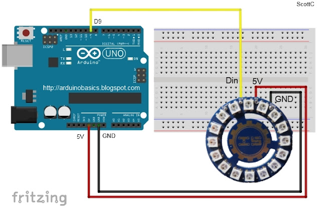
Fritzing diagram

Connecting ONE LED Ring to the Arduino- (Click to enlarge)


  • 3 wires: You only need 3 wires to connect to the LED ring. If you only plan to light up a couple of LEDs at any one time this should be ok.
  • The SAFE WAY: A safer way to do this is to use an external power supply to power both the Arduino and the LED ring.
  • Electrolytic capacitor: By connecting a large 4700 uF 16V Electrolytic capacitor between the positive and negative terminals of power supply leads, with the negative leg of the capacitor attached to the negative terminal of the power supply, you will protect your LED rings from any initial onrush of current.


  • Protecting Resistor: It is also advisable to place a 300-400 ohm resistor between the Arduino's Digital Pin 9 (D9) and the LED Ring's Digital Input pin (Din). This protects the first LED from potential voltage spikes
  • Suitable wires: If you plan to chain a few of these LED rings together (see below), then you will probably want to keep the wires as short as possible and use a decent guage wire that can handle the current being drawn through them.


Connecting TWO LED Rings to the Arduino- (Click to enlarge)


  • Three extra wires:You only need 3 extra wires to connect an additional LED ring. A wire needs to connect the Digital output (Dout) of the first LED ring to the Digital Input (Din) of the 2nd LED ring.
  • Stay safe: Once again, a safer way to do this is to use an external power supply, a large electrolytic capacitor at the terminals, and a 300-400 ohm resistor between the Arduino and the first LED ring's digital input pin.


Connecting FOUR LED Ring to the Arduino- (Click to enlarge)


  • Sixty Four LEDs:You need 3 extra wires for each additional LED ring. 4 LED rings provides a total of 64 LEDs.
  • Watch the AMPS:At full brightness, this setup could potentially draw up to 4amps (or roughly 1 amp per LED ring)
  • External Supply essential: It is essential to use an external power supply to power these LEDs when there are so many of them. If you don't use an external power supply and you accidentally illuminate ALL of the LEDs, then you are likely to damage the microcontroller from excessive current draw.


Connection Tables

How to connect ONE LED Ring to the Arduino- (Click to enlarge)


How to connect TWO LED Rings to the Arduino- (Click to enlarge)


Concluding comments

In this tutorial I showed you how to go about decorating a Disco Ball cake and also showed you how to use the RGB LED rings from ICStation. If you look at the video you will see just how versatile these LED rings are. I would like to thank my wife for providing such an exciting project to work on, and ICStation for their collaborative efforts. Please make sure to share this project with all of your friends and family.


If you like this page, please do me a favour and show your appreciation :

 
Visit my ArduinoBasics Google + page.
Follow me on Twitter by looking for ScottC @ArduinoBasics.
I can also be found on Pinterest and Instagram.
Have a look at my videos on my YouTube channel.


Description: Arduino Disco Ball Cake Rating: 3.5 Reviewer: Unknown ItemReviewed: Arduino Disco Ball Cake
Bluetooth Android Processing 4 Reviewed by Unknown on 00:23 Rating: 4.5

Bluetooth Android Processing 4

PART FOUR

The Video


This is part 4 of my tutorial on designing an Android Phone Bluetooth App using the Android/Processing language. The App sends information to an Arduino via Bluetooth after pressing a button on the phone. The RGB LED attached to the Arduino Uno (or compatible board) will change colour depending on the button being pressed on the phone. The Arduino gains Bluetooth capabilities through the Seeedstudio Bluetooth shield (which can be found here).

Parts 1-3 of the tutorial were designed to take you step-by-step through designing the app. If you are wondering what you missed, here is a summary:

This is what you'll find in partone:
  • Downloading and setting up the Android SDK
  • Downloading the Processing IDE
  • Setting up and preparing the Android device
  • Running through a couple of Processing/Android sketches on an Andoid phone.

This is what you will find in part two:

  • Introducing Toasts (display messages)
  • Looking out for BluetoothDevices using BroadcastReceivers
  • Getting useful information from a discovered Bluetooth device
  • Connecting to a Bluetooth Device
  • An Arduino Bluetooth Sketch that can be used in this tutorial

This is what you will find in part three:

  • InputStreams and OutputStreams
  • Error Logs using logcat
  • Testing the InputStreams and OutputStreams
  • Using the APWidgets library to create buttons
  • Adding Buttons to the BlueTooth Project


In Part 4, we simplify and strip down the App so that it will only sends a specific String to the Arduino via Bluetooth. The String sent to the Arduino depends on the Button being pressed. The code has been cleaned up and has many comments to help you understand what is going on. You should be able to run this sketch without having to go back through parts one, two or three of the tutorial. This fourth part of the tutorial was designed for those people who want the final end product, and are happy to work it out for themselves. I hope this serves you well.
I will therefore assume that you have already setup your phone and have downloaded all the neccesary drivers, libraries, SDKs and IDEs. If not, then here are a few quick links:
If you are a bit lost and want want a bit more information then please go through parts one, two and three of this tutorial.
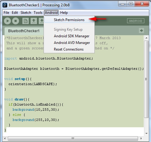
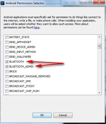
Make sure that you have selected the Bluetooth permissions as per the following:

  • Android > Sketch permissions  (as per the picture below)


Make sure that BLUETOOTH and BLUETOOTH_ADMIN are selected (as per the picture below). Then press the OK button.


Then copy and paste the following sketch into the processing/android IDE:

Android/Processing Sketch 9: Bluetooth App2

 1
2
3
4
5
6
7
8
9
10
11
12
13
14
15
16
17
18
19
20
21
22
23
24
25
26
27
28
29
30
31
32
33
34
35
36
37
38
39
40
41
42
43
44
45
46
47
48
49
50
51
52
53
54
55
56
57
58
59
60
61
62
63
64
65
66
67
68
69
70
71
72
73
74
75
76
77
78
79
80
81
82
83
84
85
86
87
88
89
90
91
92
93
94
95
96
97
98
99
100
101
102
103
104
105
106
107
108
109
110
111
112
113
114
115
116
117
118
119
120
121
122
123
124
125
126
127
128
129
130
131
132
133
134
135
136
137
138
139
140
141
142
143
144
145
146
147
148
149
150
151
152
153
154
155
156
157
158
159
160
161
162
163
164
165
166
167
168
169
170
171
172
173
174
175
176
177
178
179
180
181
182
183
184
185
186
187
188
189
190
191
192
193
194
195
196
197
198
199
200
201
202
203
204
205
206
207
208
209
210
211
212
213
214
215
216
217
218
219
220
221
222
223
224
225
226
227
228
229
230
231
232
233
234
235
236
237
238
239
240
241
242
243
244
245
246
247
248
249
250
251
252
253
254
255
256
257
258
259
260
261
262
263
264
265
266
267
268
269
270
271
272
273
274
275
276
277
278
279
280
281
282
283
284
285
286
287
288
289
290
291
292
293
294
295
296
297
298
299
300
301
302
303
304
305
306
307
308
309
310
311
312
313
314
315
316
317
318
319
320
321
322
323
324
325
326
327
328
329
330
331
332
333
334
335
336
337
338
/* BluetoothApp2: Written by ScottC on 1st April 2013 using 
Processing version 2.0b8
Tested on a Samsung Galaxy SII, with Android version 2.3.4
Android ADK - API 10 SDK platform
Apwidgets version: r44 : http://code.google.com/p/apwidgets/
*/


/*------------------------------------------------------------------------------
IMPORT statements required for this sketch
-----------------------------------------------------------------------------*/
import android.content.BroadcastReceiver;
import android.content.Context;
import android.content.Intent;
import android.content.IntentFilter;

import android.bluetooth.BluetoothAdapter;
import android.bluetooth.BluetoothDevice;
import android.bluetooth.BluetoothSocket;

import java.io.IOException;
import java.io.OutputStream;
import java.util.UUID;
import android.util.Log;

import apwidgets.APWidgetContainer;
import apwidgets.APButton;
import apwidgets.APWidget;
import apwidgets.OnClickWidgetListener;


/*------------------------------------------------------------------------------
GLOBAL Variables to be used between a number of classes.
-----------------------------------------------------------------------------*/
public int[] bg={0,80,0};
public BluetoothDevice btShield = null;
public BluetoothSocket btSocket = null;
public OutputStream btOutputStream = null;
public APWidgetContainer widgetContainer=null;
public Connect2BtDevice ConBTdevice=new Connect2BtDevice();


/*------------------------------------------------------------------------------
The following variables are used to setup the Buttons used in the GUI
of the phone. It includes the variables that determine the
- text on the buttons
- the number of buttons
- the letters that will be sent to Arduino when the buttons are pressed
- the colour that the background will change to when the buttons are pressed
- the dimensions of the buttons (width and height)
- The gap between each button
-----------------------------------------------------------------------------*/
String[] buttonText = { "RED", "GREEN", "BLUE", "OFF"}; //Button Labels
String[] sendLetter={"r","g","b","x"}; //Letters to send when button pressed
int n= buttonText.length; //Number of buttons
int[][] buttonColour = { {255,10,10},
{10,255,10},
{10,10,255},
{0,0,0}
}; //The Background colour on phone when button pressed


APButton[] guiBtns = new APButton[n]; //Array of buttons
int gap=10; //gap between buttons
int buttonWidth=0; //initialising the variable to hold the WIDTH of each button
int buttonHeight=0; //initialising the variable to hold the HEIGHT of each button


/*------------------------------------------------------------------------------
The setup() method is used to connect to the Bluetooth Device, and setup
the GUI on the phone.
-----------------------------------------------------------------------------*/
void setup(){
new Thread(ConBTdevice).start(); //Connect to SeeedBTSlave device
orientation(LANDSCAPE); //Make GUI appear in landscape mode

//Setup the WidgetContainer and work out the size of each button
widgetContainer = new APWidgetContainer(this);
buttonWidth=((width/n)-(n*(gap/2))); //button width depends on screen width
buttonHeight=(height/2); //button height depends on screen height

//Add ALL buttons to the widgetContainer.
for(int i=0; i<n;i++){
guiBtns[i]= new APButton(((buttonWidth*i)+(gap*(i+1))), gap, buttonWidth, buttonHeight, buttonText[i]);
widgetContainer.addWidget(guiBtns[i]);
}
}


/*------------------------------------------------------------------------------
The draw() method is only used to change the colour of the phone's background
-----------------------------------------------------------------------------*/
void draw(){
background(bg[0],bg[1],bg[2]);
}


/*------------------------------------------------------------------------------
onClickWidget is called when a button is clicked/touched, which will
change the colour of the background, and send a specific letter to the Arduino.
The Arduino will use this letter to change the colour of the RGB LED
-----------------------------------------------------------------------------*/
void onClickWidget(APWidget widget){
String letrToSend="";

/*Identify the button that was pressed, Change the phone background
colout accordingly and choose the letter to send */
for(int i=0; i<n;i++){
if(widget==guiBtns[i]){
ConBTdevice.changeBackground(buttonColour[i][0],
buttonColour[i][1],
buttonColour[i][2]);
letrToSend=sendLetter[i];
}
}

/* Send the chosen letter to the Arduino/Bluetooth Shield */
if(ConBTdevice!=null){
ConBTdevice.write(letrToSend);
}
}


/*==============================================================================
CLASS: Connect2BtDevice implements Runnable
- used to connect to remote bluetooth device and send values to the Arduino
==================================================================================*/
public class Connect2BtDevice implements Runnable{

/*------------------------------------------------------------------------------
Connect2BtDevice CLASS Variables
-----------------------------------------------------------------------------*/
BluetoothAdapter btAdapter=null;
BroadcastReceiver broadcastBtDevices=null;
private UUID uuid = UUID.fromString("00001101-0000-1000-8000-00805F9B34FB");


/*------------------------------------------------------------------------------
DEFAULT CONSTRUCTOR: Connect2BtDevice()
- Create a BroadcastReceiver (registered in run() method).
- Get the default Bluetooth Adapter
- Enable the adapter (if it is not already enabled).
- Discover available Bluetooth devices to connect to
-----------------------------------------------------------------------------*/
public Connect2BtDevice(){
broadcastBtDevices = new btBroadcastReceiver();
getBtAdapter();
enableBtAdapter();
discoverBtDevices();
}


/*------------------------------------------------------------------------------
run() method
- used to register the broadcast receiver only
-----------------------------------------------------------------------------*/
@Override
public void run() {
registerReceiver(broadcastBtDevices, new IntentFilter(BluetoothDevice.ACTION_FOUND));
}


/*------------------------------------------------------------------------------
getBtAdapter() method
- get the default Bluetooth adapter
-----------------------------------------------------------------------------*/
void getBtAdapter(){
btAdapter = BluetoothAdapter.getDefaultAdapter();
}


/*------------------------------------------------------------------------------
enableBtAdapter() method
- Enable the default Bluetooth Adapter if it isn't already enabled
-----------------------------------------------------------------------------*/
void enableBtAdapter(){
if (!btAdapter.isEnabled()) {
btAdapter.enable();
}
}


/*------------------------------------------------------------------------------
discoverBtDevices() method
- Discover other Bluetooth devices within range (ie SeeedBTSlave device)
-----------------------------------------------------------------------------*/
void discoverBtDevices(){
while(!btAdapter.isEnabled()){
//Wait until the Bluetooth Adapter is enabled before continuing
}
if (!btAdapter.isDiscovering()){
btAdapter.startDiscovery();
}
}


/*------------------------------------------------------------------------------
connect2Bt() method: called by the btBroadcastReceiver
- Create a BluetoothSocket with the discovered Bluetooth device
- Change background to yellow at this step
- Connect to the discovered Bluetooth device through the BluetoothSocket
- Wait until socket connects then
- Attach an outputStream to the BluetoothSocket to communicate with Bluetooth
device. (ie. Bluetooth Shield on the the Arduino)
- Write a "g" string through the outputStream to change the colour of the LED
to green and change the phone background colour to green also.
A green screen and green LED suggests a successful connection, plus the
Bluetooth shield's onboard LED starts flashing green slowly (1 per second),
which also confirms the successful connection.
-----------------------------------------------------------------------------*/
void connect2Bt(){
try{
btSocket = btShield.createRfcommSocketToServiceRecord(uuid);
changeBackground(255,255,0); //YELLOW Background
try{
btSocket.connect();
while(btSocket==null){
//Do nothing
}
try {
btOutputStream = btSocket.getOutputStream();
changeBackground(0,255,0); //Green Background
write("g"); //Green LED (Successful connection)
}catch (IOException e) {
Log.e("ConnectToBluetooth", "Error when getting output Stream");
}
}catch(IOException e){
Log.e("ConnectToBluetooth", "Error with Socket Connection");
changeBackground(255,0,0); //Red background
}
}catch(IOException e){
Log.e("ConnectToBluetooth", "Error with Socket Creation");
changeBackground(255,0,0); //Red background
try{
btSocket.close(); //try to close the socket
}catch(IOException closeException){
Log.e("ConnectToBluetooth", "Error Closing socket");
}return;
}
}


/*------------------------------------------------------------------------------
write(String str) method
- Allows you to write a String to the remote Bluetooth Device
-----------------------------------------------------------------------------*/
public void write(String str) {
try {
btOutputStream.write(stringToBytes(str));
} catch (IOException e) {
Log.e("Writing to Stream", "Error when writing to btOutputStream");
}
}


/*------------------------------------------------------------------------------
byte[] stringToBytes(String str) method
- Used by the write() method
- This method is used to convert a String to a byte[] array
- This code snippet is from Byron:
http://www.javacodegeeks.com/2010/11/java-best-practices-char-to-byte-and.html
-----------------------------------------------------------------------------*/
public byte[] stringToBytes(String str) {
char[] buffer = str.toCharArray();
byte[] b = new byte[buffer.length << 1];
for(int i = 0; i < buffer.length; i++) {
int bpos = i << 1;
b[bpos] = (byte) ((buffer[i]&0xFF00)>>8);
b[bpos + 1] = (byte) (buffer[i]&0x00FF);
}
return b;
}


/*------------------------------------------------------------------------------
cancel() method
- Can be called to close the Bluetooth Socket
-----------------------------------------------------------------------------*/
public void cancel() {
try {
btSocket.close();
} catch (IOException e){
}
}


/*------------------------------------------------------------------------------
changeBackground(int bg0, int bg1, int bg2) method
- A method to change the background colour of the phone screen
-----------------------------------------------------------------------------*/
void changeBackground(int bg0, int bg1, int bg2){
bg[0] = bg0;
bg[1] = bg1;
bg[2] = bg2;
}
}


/*==============================================================================
CLASS: btBroadcastReceiver extends BroadcastReceiver
- Broadcasts a notification when the "SeeedBTSlave" is discovered/found.
- Use this notification as a trigger to connect to the remote Bluetooth device
==================================================================================*/
public class btBroadcastReceiver extends BroadcastReceiver {
@Override
public void onReceive(Context context, Intent intent) {
String action=intent.getAction();
/* Notification that BluetoothDevice is FOUND */
if(BluetoothDevice.ACTION_FOUND.equals(action)){
/* Get the discovered device Name */
String discoveredDeviceName = intent.getStringExtra(BluetoothDevice.EXTRA_NAME);

/* If the discovered Bluetooth device Name =SeeedBTSlave then CONNECT */
if(discoveredDeviceName.equals("SeeedBTSlave")){
/* Get a handle on the discovered device */
btShield = intent.getParcelableExtra(BluetoothDevice.EXTRA_DEVICE);
/* Connect to the discovered device. */
ConBTdevice.connect2Bt();
}
}
}
}


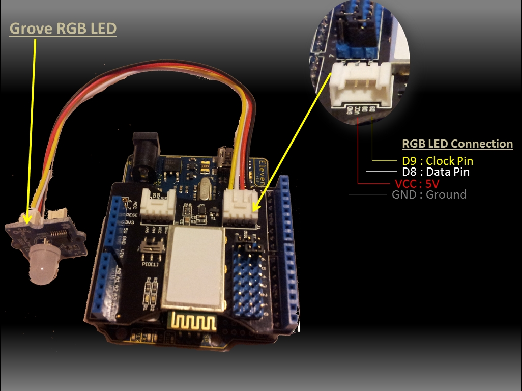
Here is a picture of the components used in this sketch:
Bluetooth Shield with Grove RGB LED


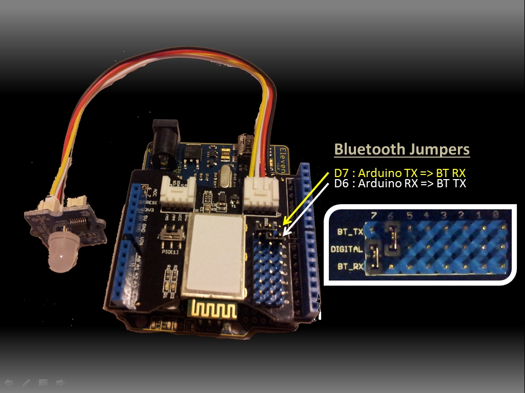
Please take notice of the Jumper pin placement on the Bluetooth Shield. This ensures communication between the Arduino and Bluetooth Shield, and is reflected in the Arduino code further down this page. The Arduino transmits information to the Bluetooth Shield on Digital pin 7, and therefore the Bluetooth Shield receivesinformation from the Arduino on Digital pin 7. On the other hand, the Bluetooth shield transmits and the Arduino receives information on Digital pin 6 (see picture below).  This serial communication between the Arduino and the Bluetooth Shield occurs through the SoftwareSeriallibrary. This is different from the Serial library used in some of my other tutorials (often to display information in the Serial Monitor). The Arduino UNO's Serial pins are 0 (RX) and 1 (TX). It is worth looking at the Arduino Serialpage if you happen to have an Arduino Leonardo, because there are some differences that you should take into consideration when running this sketch.


Jumpers on Shield


Make sure that your Arduino has the following code installed and running BEFORE you launch the Android/Processing Sketch on your Android Device. If you don't do it in this order, your Android phone will not discover the Bluetooth Device attached to the Arduino, and you will waste a lot of time. Make sure that the Bluetooth shield is flashing it's red/green LEDs. Once you see this alternating red/green LED display, launch the Android/Processing sketch on the Android device. When you see the chainable RGB LED turn from white to green, you know you have a successful connection. You may then press the GUI buttons on the Android phone to change the colour of the LED to either Red, Green, Blue or Off.

Arduino Sketch 3: Bluetooth RGB Colour Changer (with OFF option)
2
3
4
5
6
7
8
9
10
11
12
13
14
15
16
17
18
19
20
21
22
23
24
25
26
27
28
29
30
31
32
33
34
35
36
37
38
39
40
41
42
43
44
45
46
47
48
49
50
51
52
53
54
55
56
57
58
59
60
61
62
63
64
65
66
67
68
69
70
71
72
73
74
75
76
77
78
79
80
81
82
83
84
85
86
87
88
89
90
91
92
93
94
95
96
97
98
99
100
101
102
103
104
105
106
107
108
109
110
111
112
113
114
115
116
117
118
119
120
121
122
123
124
125
126
127
128
129
130
131
132
133
134
135
136
137
138
139
140
141
142
143
144
145
146
147
148
149
150
151
152
153
154
155
156
157
158
159
160
161
162
163
164
165
166
167
168
/* This project combines the code from a few different sources.
This project was put together by ScottC on the 15/01/2013
http://arduinobasics.blogspot.com/

Bluetooth slave code by Steve Chang - downloaded from :
http://www.seeedstudio.com/wiki/index.php?title=Bluetooth_Shield

Grove Chainable RGB code can be found here :
http://www.seeedstudio.com/wiki/Grove_-_Chainable_RGB_LED#Introduction

Updated on 25 March 2013: Receive 'x' to turn off RGB LED.

*/


#include <SoftwareSerial.h>
//Software Serial Port

#define uint8
unsigned char
#define uint16
unsigned int
#define uint32
unsigned long int

#define RxD 6
// This is the pin that the Bluetooth (BT_TX) will transmit to the Arduino (RxD)
#define TxD 7
// This is the pin that the Bluetooth (BT_RX) will receive from the Arduino (TxD)

#define DEBUG_ENABLED 1

int Clkpin = 9; //RGB LED Clock Pin (Digital 9)
int Datapin = 8; //RGB LED Data Pin (Digital 8)

SoftwareSerial blueToothSerial(RxD,TxD);
/*----------------------SETUP----------------------------*/ void setup() {
Serial.begin(9600);
// Allow Serial communication via USB cable to computer (if required)
pinMode(RxD, INPUT);
// Setup the Arduino to receive INPUT from the bluetooth shield on Digital Pin 6
pinMode(TxD, OUTPUT);
// Setup the Arduino to send data (OUTPUT) to the bluetooth shield on Digital Pin 7
pinMode(13,OUTPUT);
// Use onboard LED if required.
setupBlueToothConnection();
//Used to initialise the Bluetooth shield

pinMode(Datapin, OUTPUT);
// Setup the RGB LED Data Pin
pinMode(Clkpin, OUTPUT);
// Setup the RGB LED Clock pin

}
/*----------------------LOOP----------------------------*/ void loop() {
digitalWrite(13,LOW);
//Turn off the onboard Arduino LED
char recvChar;
while(1){
if(blueToothSerial.available()){//check if there's any data sent from the remote bluetooth shield
recvChar = blueToothSerial.read();
Serial.print(recvChar);
// Print the character received to the Serial Monitor (if required)

//If the character received = 'r' , then change the RGB led to display a RED colour
if(recvChar=='r'){
Send32Zero();
// begin
DataDealWithAndSend(255, 0, 0);
// first node data
Send32Zero();
// send to update data
}

//If the character received = 'g' , then change the RGB led to display a GREEN colour
if(recvChar=='g'){
Send32Zero();
// begin
DataDealWithAndSend(0, 255, 0);
// first node data
Send32Zero();
// send to update data
}

//If the character received = 'b' , then change the RGB led to display a BLUE colour
if(recvChar=='b'){
Send32Zero();
// begin
DataDealWithAndSend(0, 0, 255);
// first node data
Send32Zero();
// send to update data
}

//If the character received = 'x' , then turn RGB led OFF
if(recvChar=='x'){
Send32Zero();
// begin
DataDealWithAndSend(0, 0, 0);
// first node data
Send32Zero();
// send to update data
}
}

//You can use the following code to deal with any information coming from the Computer (serial monitor)
if(Serial.available()){
recvChar = Serial.read();

//This will send value obtained (recvChar) to the phone. The value will be displayed on the phone.
blueToothSerial.print(recvChar);
}
}
}

//The following code is necessary to setup the bluetooth shield ------copy and paste----------------
void setupBlueToothConnection()
{
blueToothSerial.begin(38400);
//Set BluetoothBee BaudRate to default baud rate 38400
blueToothSerial.print("
\r\n+STWMOD=0\r\n"); //set the bluetooth work in slave mode
blueToothSerial.print("
\r\n+STNA=SeeedBTSlave\r\n"); //set the bluetooth name as "SeeedBTSlave"
blueToothSerial.print("
\r\n+STOAUT=1\r\n"); // Permit Paired device to connect me
blueToothSerial.print("
\r\n+STAUTO=0\r\n"); // Auto-connection should be forbidden here
delay(2000);
// This delay is required.
blueToothSerial.print("
\r\n+INQ=1\r\n"); //make the slave bluetooth inquirable
Serial.println("
The slave bluetooth is inquirable!");
delay(2000);
// This delay is required.
blueToothSerial.flush();
}

//The following code snippets are used update the colour of the RGB LED-----copy and paste------------
void ClkProduce(void){
digitalWrite(Clkpin, LOW);
delayMicroseconds(20);
digitalWrite(Clkpin, HIGH);
delayMicroseconds(20);
}
void Send32Zero(void){
unsigned char i;
for (i=0; i<32; i++){
digitalWrite(Datapin, LOW);
ClkProduce();
}
}

uint8 TakeAntiCode(uint8 dat){
uint8 tmp = 0;
if ((dat & 0x80) == 0){
tmp |= 0x02;
}

if ((dat & 0x40) == 0){
tmp |= 0x01;
}

return tmp;
}
// gray data
void DatSend(uint32 dx){
uint8 i;
for (i=0; i<32; i++){
if ((dx & 0x80000000) != 0){
digitalWrite(Datapin, HIGH);
}
else {
digitalWrite(Datapin, LOW);
}

dx <<= 1;
ClkProduce();
}
}
// data processing
void DataDealWithAndSend(uint8 r, uint8 g, uint8 b){
uint32 dx = 0;

dx |= (uint32)0x03 << 30;
// highest two bits 1,flag bits
dx |= (uint32)TakeAntiCode(b) << 28;
dx |= (uint32)TakeAntiCode(g) << 26;
dx |= (uint32)TakeAntiCode(r) << 24;

dx |= (uint32)b << 16;
dx |= (uint32)g << 8;
dx |= r;

DatSend(dx);
}


Please note that this Arduino code/project will work with SeeedStudio's Bluetooth Shield.  You may need to modify the Arduino Code (lines 95-107) to coincide with your own bluetooth shield. I got the code snippet within the my setupBlueToothConnection() method from some example code from Steve Chang which was found on SeeedStudio's Bluetooth Shield Wiki page. Here is some other useful information in relation to setting up this Bluetooth Shield that could be of help in your project (here).

Much of the code used within the Android/Processing sketch was made possible through constant reference to these sites:
And I would also like to thank Pauline303 who made the suggestion within the Processing Forums to use APWidgets Library for my Buttons in the App.
The Arduino and Processing Forums are always a great place to get help in a short amount of time.


Description: Bluetooth Android Processing 4 Rating: 3.5 Reviewer: Unknown ItemReviewed: Bluetooth Android Processing 4
Back to top