.
Nextion Enhanced Stepper Motor Piano Project Reviewed by Unknown on 09:12 Rating: 4.5

Nextion Enhanced Stepper Motor Piano Project


Introduction


Nextion is a programmable human machine interface (HMI) that can be customized and designed to simplify the interaction between you and your project.
This Nextion Enhanced module (NX4827K043) with a resistive touch screen display, has some additional features not seen in previous traditional versions of the Nextion series.

  • A built in real time clock (RTC)
  • Accessible flash memory (32MB)
  • GPIO functionality
  • Faster clock speed

Before you connect the Nextion Enhanced module to your project, you need to design your interface with the free Nextion Editor. The editor can be downloaded here.
In this project, I will be designing a simple dynamic interface, which will allow me to interact with a stepper motor in two different ways.
The first interface will let me control the direction and speed of the stepper motor through the use of a simple GUI. I will have left and right arrows for the direction, and up and down arrows for the speed. I will also map the Expansion board to this interface for a more tactile experience.
The second interface will be more musical in nature. I will design a functional “Stepper motor piano” that will allow me to play simple songs using the rotational sounds of the stepper motor. This concept is not new, but I will show you how easy it is to make.


Project Scope


My project will show a splash screen when the project is powered up. After 3 seconds, the first interface will display.
The first interface will have 4 arrows:

  1. Left and Right arrows for the stepper motor direction of rotation
  2. Up and down arrows to increase/decrease stepper motor rotational speed
  3. Next Page button – to jump to the next interface

Each arrow/button on the first interface will be mapped to a specific button on the expansion board. Eg.

  1. Left/Right arrow is mapped to Left/Right button
  2. Up/Down arrow is mapped to Up/Down button
  3. Next page button is mapped to Enter button on the expansion board

The second interface will look like a piano on the Nextion Enhanced display. Each key on the piano will transmit a specific and unique number to the Arduino.
The specific number received by the Arduino will allow it to set the speed of stepper motor which will ultimately affect the frequency of sound it produces. Therefore when the “C” key is pressed on the Nextion display, the stepper motor will rotate at a frequency that sounds like a “C” note.
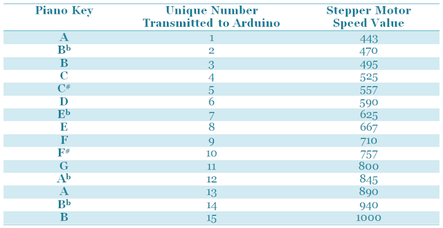
Table describes the stepper motor speed value and the number that is transmitted to the Arduino for each piano key


The stepper motor speeds can be determined by tuning the motor to specific notes using the first interface and an iPhone app called Tuner T1 Free".
If you plan to replicate this project, you will need to determine the relevant speeds of your own stepper motor, and substitute your values into the Arduino code later on in this tutorial.


Create a New Project


The first step is to create the interfaces in the Nextion Editor on your PC. You can download the Nextion Editor here.. Load up the Nextion Editor and create a new project.
When you start a new project, you need to make sure that you select the correct Nextion device from the available options.
I am using the “Nextion Enhanced NX4827K043” device.

  1. Select File → New
  2. Select a name for the project and save it to a suitable place on the hard drive
  3. Select the appropriate Nextion device from the available options
    1. My device has a screen size of 480 x 272 pixels
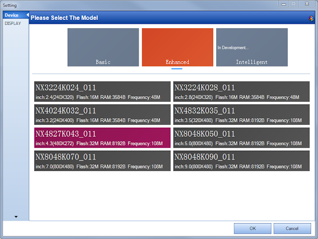

Selection of the NX4827K043_011 module from other available selections


Project Resources


You need to import all of the resources (eg. pictures and fonts) into your project, and then design the interface to suit your specific needs.

Fonts


I will not be using any fonts in my project, but if you wanted to write any text to the display, you will need to generate a font in the Nextion Editor.

  1. Tools → Font Generator
    1. Select the Height of the Font (eg. 16)
    2. Select the Font code type (eg. iso-8859-2)
    3. Select if you want it to be in Bold or not
    4. Choose the Font you want to use (eg. Arial)
    5. Choose the spacing (eg. 0)
    6. And finally give this Font a unique name (e.g. Arial_16)
    7. Push the “Generate Font” button on the bottom right of the window


Dialog box for the font generator in the Nextion Editor

Once you press the Generate Font button, it will get you to save the font using a *.zi extension, and will automatically ask you if you would like to “Add the generated font?” to the project. If you are happy with the font, and would like to use this font in your project, then select “Yes”, otherwise select “No” and start again.

Font generator acknowledgement, dialog box

You cannot add any text to your project until you have imported or added a font. All of your project fonts will be displayed in the fonts window.

A list of available fonts in the Nextion editor (arduinobasics.blogspot.com)

Each font will automatically be indexed, so that you can reference the font programmatically if required. In fact all resources that you add to your project are assigned a number and incremented by one for every resource added. For some resources, you can see this number to the left of the item. E.g. In the picture above, the Courier Font has an index of 0, whereas the Arial font has an index of 1. If you delete a resource, the index number may change for that item.


Pictures


As I said before, I will not be using any fonts for my project because the words on the screen will not be changing in any way. I can get away with designing a “Picture” and importing that into the project. I will need 3 pictures for my project.

  1. Splash screen
  2. Stepper Motor Controller
  3. Stepper Motor Piano

On the Nextion Enhanced NX4827K043 device, each picture must be

  • 480 x 272 pixels in size

We will now import the following pictures into the Nextion Editor so that we can use them in the project.
In the bottom left hand corner of the Nextion editor is the “Fonts and Picture” resource window:

  1. Select the Picture tab
  2. Then select the “+” icon
  3. This will open a dialog box to allow you to select the picture(s) to add to the project. You can select more than one picture to import.

I imported the following pictures from my computer:


Splash Screen



ArduinoBasics Splash Screen image (arduinobasics.blogspot.com)


Interface 1: Stepper Motor Controller
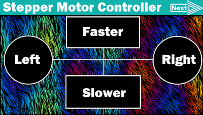


Stepper Motor Controller Background Image for Interface (arduinobasics.blogspot.com)


Interface 2: Stepper Motor Piano


Stepper Motor Piano Background Image for Interface 2 (arduinobasics.blogspot.com)


Creating the GUI


Pages


Every resource will get an ID based on the order it is added, and each resource will automatically get a name. You can change the name of the resource or object, but you cannot edit the ID.
Three pages will be designed to meet the criteria described above.
To add a page, you simply select the “Add” icon from the “page window”. And keep adding pages until you have a total of 3 pages (page0, page1 and page2).
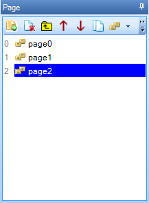
Add pages to the project in the Nextion Editor (arduinobasics.blogspot.com)


Page 0 - Splash Screen


When the Nextion is powered up, the splash screen will be displayed for 3 seconds before it shows the Stepper Motor Controller screen. I used the following steps to create the splash screen.

  1. Add the splash screen picture to page0
    1. Select “page0” from the Page window
    2. Select “Picture” from the Toolbox window
    3. Double-click the “pic” attribute from the Attribute window
    4. Select the splash screen image from the list
    5. Press the OK button
  2. Add a Timer to page0
    1. Select Timer from the Toolbox window
    2. Change the “tim” attribute from 400 to 3000 in the Attribute window
    3. Enter “page page1” in the User code section of the Timer Event(0)

This timer event will make the Nextion jump to page1 after 3 seconds.
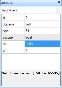
Attributes of the Timer Event in the Nextion Editor (arduinobasics.blogspot.com)


Page 1 - Stepper Motor Controller


This page is designed to control the direction and speed of the stepper motor.
There will be two buttons for the direction (Left and Right), and two buttons for the speed (Faster and Slower). And one more button to jump to the next page (i.e. the Stepper Motor Piano page). These buttons will also be mapped to the Nextion expansion board. The tactile buttons of the expansion board will provide an alternative method of controlling the motor.

  1. Add the Stepper Motor Controller picture to page1
    1. Select “page1” from the Page window
    2. Select “Picture” from the Toolbox window
    3. Double-click the “pic” attribute from the Attribute window
    4. Select the “Stepper Motor Controller” image from the list
    5. Press the OK button
  2. Add Hotspots over each button on the Stepper Motor Controller image
    1. Select “Hotspot” from the Toolbox window
    2. Drag and resize the Hotspot so that it covers the “Left” button
      1. This is the area that will respond to “Left button” presses.
      2. It will be transparent when uploaded to the Nextion board
    3. Select the “Touch Press Event” tab in the Event window
    4. Un-Check the “Send Component ID” checkbox
    5. Type the following code into the “User Code” Section of the Event window:
      • print “L”
    6. Change the object name of the hotspot to “Left” using the following process:
      1. Select objname from the attribute window and change the text from “m0” to “Left”
      2. It is not compulsory to change the hotspot object name; however it will help later on.
    7. Repeat steps 2a-2f for each of the other buttons in the following order and as per the table below
      1. Right
      2. Faster
      3. Slower
      4. Next

Shows how to program each button on the first inteface of this project in the Nextion Editor (arduinobasics.blogspot.com)

The decimal ASCII code for the letter “L” is 76, hence when the Nextion Enhanced display sends the letter L to the Arduino using the print “L” command, the Arduino will receive the number 76. When the right button is pressed, it will receive the number 82, and so on.
The “Next” button does not transmit anything to the Arduino, it is simply there to jump to the next interface on the Nextion Enhanced display, hence the reason why the user code is different for that button.
  1. Map the buttons to the Expansion board
    1. Select “page0” and then “page1” from the Page window

    2. Select Page 1 in the Nextion Editor (arduinobasics.blogspot.com)

    3. Select the “Preinitialize Event” tab from the Event window
    4. Enter the following code into the “User Code” field of the Preinitialize Event tab:
      • cfgpio 5,1,Left
      • cfgpio 2,1,Right
      • cfgpio 4,1,Faster
      • cfgpio 3,1,Slower
      • cfgpio 1,1,Next

User code for the preinitialize event box in page1 (arduinobasics.blogspot.com)

Please note: There is one space between cfgpio and the number next to it, but there are no other spaces on each line. If you introduce extra spaces, it will not compile.
This code maps the buttons on the expansion board to the hotspot objects on page1. For example, when the Left button (IO5) on the expansion board is pressed, it simulates the actions or events associated with hotspot m0/Left. In this case it will send a value of “L” (76) to the Arduino.

Expansion Board Buttons (arduinobasics.blogspot.com)

The IO number is marked within brackets on the expansion board.
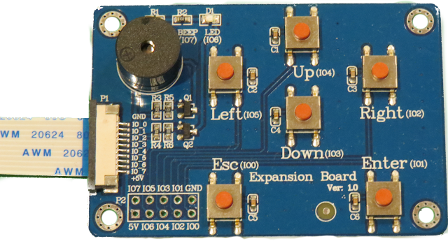
Expansion Board (arduinobasics.blogspot.com)


Page 2 - Stepper Motor Piano


This interface will be designed to look like a piano, and will allow me to control the stepper motor such that it produces a note in the same key as the one I press on the Nextion display. The stepper motor will produce the note by rotating at a specific frequency.

  1. Add the Stepper Motor Piano picture to page2
    1. Select “page2” from the Page window
    2. Select “Picture” from the Toolbox window
    3. Double-click the “pic” attribute from the Attribute window
    4. Select the “Stepper Motor Piano” image from the list
    5. Press the OK button
  2. Add Hotspots over each key on the Stepper Motor Piano image
    1. Select “Hotspot” from the Toolbox window
    2. Drag and resize the Hotspot so that it covers the the “A” key.
      1. This is the area that will respond to “A-key” presses.
      2. It will be transparent when uploaded to the Nextion board
    3. Select the “Touch Press Event” tab in the Event window
    4. Type the following into the “User Code” section
      • print 1
    5. Repeat steps 2a-2d for each of the other keys as per the table below
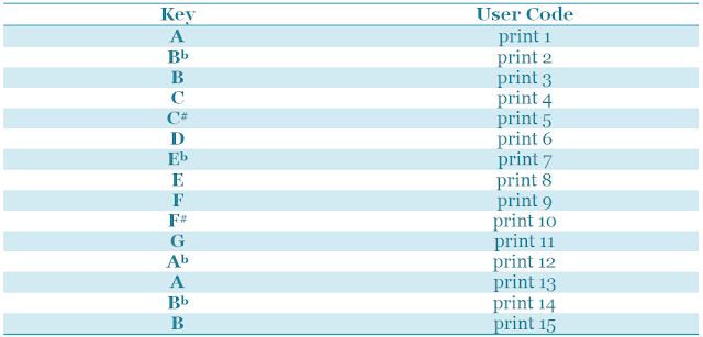
The User code for each key in interface two (arduinobasics.blogspot.com)

When the specific key is pressed, the Nextion Enhanced board will transmit the printed number, followed by three 0x00 values. The terminating values can be ignored.
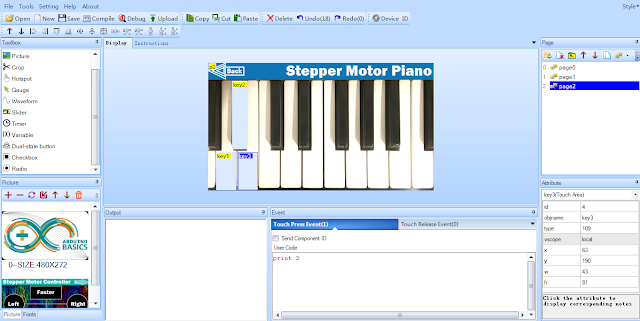
Designing the second interface in the Nextion Editor (arduinobasics.blogspot.com)

  1. The “Back” button will allow me to jump back to the previous interface on the Nextion Enhanced board.
    1. Create a hotspot for the back button using the following process:
      1. Select Hotspot from the Toolbox window
      2. Move/Resize the hotspot over the “Back” button
    2. Select the Event window
    3. Make sure the “Touch press event” tab is selected
    4. Type:   page page1   into the User Code section


Debugging


The good thing about the Nextion Editor, is that you can test out the interface functionality before uploading it to the board.

Nextion Editor Menu Items (arduinobasics.blogspot.com)


  1. Save the project by pressing the save button on the task bar
  2. Then press the compile button
  3. Then press the debug button.

A Nextion emulator window will appear. This window should respond in the same manner as Nextion module after the Nextion file is uploaded to the board. This emulator is a great way to test out your interface and to make sure it looks and works as expected. Once I was happy with the interface(s), I transferred the compiled Nextion file onto an SD card:

  1. Press the compile button
  2. File → Open Build Folder
  3. Select the *.tft file with the same name as that of the project
  4. Copy it to a micro SDHC card
  5. Insert the SDHC card into the SD card slot on the Nextion display
  6. Power up the Nextion board

Wait for the file to flash the Nextion board, and you should see a message that looks like this:
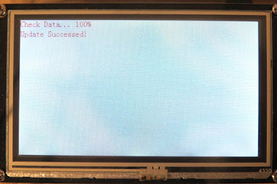
The message displayed after successful flashing of the Nextion board (arduinobasics.blogspot.com)

The next step is to power off the Nextion board, and remove the SDHC card.


ARDUINO SETUP


The Nextion Enhanced display is ready, and now it is the Arduino’s turn. The Arduino is programmed to receive Serial messages from the Nextion Enhanced display and control the stepper motor based on the letters or numbers received. The unique letters or numbers being transmitted from the Nextion board, allow the Arduino to understand what button is being pressed, and it uses those numbers or letters to control the flow of code in order to perform specific stepper motor actions.


Arduino Libraries and IDE


The Arduino IDE can be downloaded from this site.
The SoftwareSerial library is used to enable Serial communication between the Arduino and the Nextion Enhanced display.
The AccelStepper library is used to simplify the process of stepper motor control.


ARDUINO CODE:


Here is the Arduino Code for this project:
I set up a maximum and minimum speed for the motors, and some pre-defined keys. It is possible to “tune” the motor using the first interface of the Nextion display. You can do this by making the motor turn faster or slower until you reach the desired key.
I used the “Tuner T1 Free” app from the iTunes app store to identify WHEN the motor was producing a note in key.
When the motor was producing a specific note, I would write down the stepper motor speed that was printed to the Serial monitor window. Every time the motor speed is increased or decreased, the Arduino code prints the speed to the serial monitor window. I then use these speeds to update the notes[] array in the Arduino code.
The notes[] array holds the stepper motor speeds that correspond to the individual notes on the piano. The Nextion display essentially sends the index number of the note to play from the notes array on the Arduino, thereby simplifying the code required to spin the motor at 16 different speeds.


Hooking it up:


With all boards powered off, the next step is to make all of the necessary hardware connections to the Arduino. There are two major sections to consider,

  1. The Stepper motor driver and motor
  2. The Nextion Enhanced board

You need to ensure that you use an external power source to power both the stepper motor and the Nextion Enhanced board. The stepper motor driver board itself was powered by the Arduino without any problems, but the actual stepper motor will need an external power supply. The Nextion Enhanced board also needs an external power supply because it requires more current than the Arduino can safely provide.
Here is how you would connect the Arduino to the Stepper motor driver board and associated stepper motor.

Connecting up the stepper motor to the Arduino via a Stepper motor controller (arduinobasics.blogspot.com)


Connection Table showing connections between the Arduino and the Steppr motor via a Stepper motor controller (arduinobasics.blogspot.com)


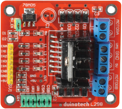
Duinotech L298 module (arduinobasics.blogspot.com)


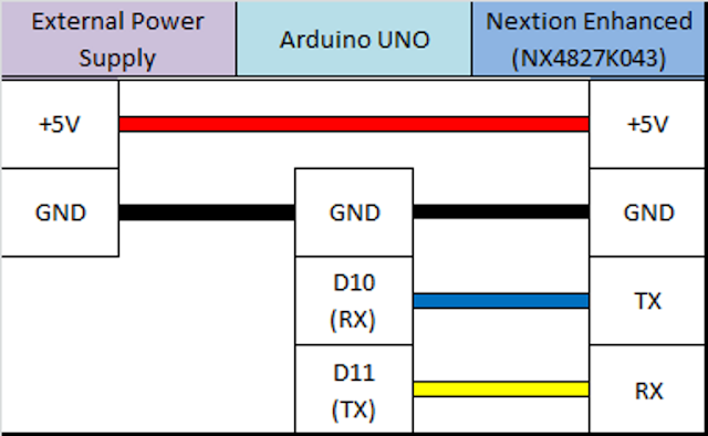
And this is how you would connect the Arduino to the Nextion Enhanced display

Diagram showing the connections between the Arduino and the Nextion Enhanced Module (arduinobasics.blogspot.com)


Table that shows the connection between the Arduino UNO and the Nextion Enhanced NX4827K043 module


Nextion Enhanced module and Expansion Board (arduinobasics.blogspot.com)


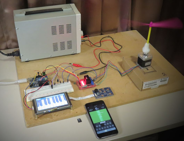
And this is what it looked like when I put it all together:

All the connections required for the stepper motor piano project (arduinobasics.blogspot.com)


Picture showing the complete setup of the Nextion Enhanced Stepper motor piano project (arduinobasics.blogspot.com)


Make note of the external power supply used. I made sure that I had a large enough power supply to handle the power requirements of the project, and utilized the relevant datasheets to help me identify those requirements. If you plan to replicate this project, make sure you take into consideration the specific power requirements of your motor, your motor driver and your Nextion display. The Arduino can only supply 400mA of current from the 5V pin.
With everything hooked up, I powered up the Nextion display, then powered up the Arduino. The stepper motor starts spinning automatically. I used the first interface to change the direction and/or speed of the motor. Please note the maximum and minimum speeds set up in the Arduino code.
I then used the Next button to jump to the second interface on the Nextion Enhanced display. The second interface looks like a piano. And when I press a key on the piano display, the motor changes speed to match the note I pressed.
Voila !! The stepper motor piano is born !!
I played a number of simple tunes on the Stepper motor piano and was surprised how well it worked. Very clever !!


Concluding comments


This project is relatively simple, but stepper motors can be tricky to set up and tune. Nothing a bit of determination cannot fix.
This project was a lot of fun. If you plan to replicate this project, I would be interested to see your versions, or just knowing if this helped you in any way.


iTead Studio Logo


This project would not have been possible without the collaborative efforts of iTead Studio. Their Nextion Enhanced display has a lot more to offer than what I have shown you here. But hopefully this tutorial gives you some insight into the power of such a display, and perhaps how it could improve the project you are currently working on. The only thing I did not like was the power requirements. I would have preferred something within Arduino power supply limits. Nevertheless, I am very happy with the Nextion Enhanced display, and would recommend it to anyone looking for a Human Machine interface to include in their project. You can see how simple it was to create TWO interfaces for my project, and I only scratched the surface.
Description: Nextion Enhanced Stepper Motor Piano Project Rating: 3.5 Reviewer: Unknown ItemReviewed: Nextion Enhanced Stepper Motor Piano Project
Arduino Disco Ball Cake Reviewed by Unknown on 13:38 Rating: 4.5

Arduino Disco Ball Cake


Description

This is a fun project that will surely impress anyone you make this for. If you are having a "Disco" themed party, you cannot have a boring old cake. Let me tell you, this is probably the only Arduino project that my wife has ever been willing to be a part of. She did the hard work of putting the cake together, and I, well.... I was in charge of lighting. My biggest fear was that one of the wires would come loose and ruin the event at the most critical moment... While a wire did come loose, I managed to fix it in time before the guests arrived. Ok enough of my monologue, let me show you how to make one of these things.


Parts Required:


Arduino Libraries and IDE

You can get the Arduino IDE from here: https://www.arduino.cc/en/Main/Software
I used version 1.6.4, which is probably way out of date... but works fine nonetheless.
 
You can get information about how to use the FastLED library here: http://fastled.io/
And you can download it from here: FastLED Library
I used version 3.0.3, which is also probably out of date.

ARDUINO CODE:

ARDUINO CODE DESCRIPTION:

  • FastLED Library: You need to make sure that you have downloaded and installed the FastLED library into your Arduino IDE. The library is included in this sketch otherwise the FastLED functions will not work.
  • The "NUM_LEDS" variable: tells the Arduino how many LEDS are in use. In this case, we have 4 LED rings, with each LED ring containing 16 LEDs, and therefore a total of 64 LEDs. If you define a lower number, for example 16, then the sketch would only illuminate the LEDs on the first LED ring.
  • The "DATA_PIN" variable: tells the Arduino which Digital Pin to use for data transmission to the LED ring. In this case, I am using Digital Pin 9.
  • Other variables: I have a couple of other variables which are used for LED randomisation and hue control. Hue is the colour of the LED. By incrementing the hue variable, you can get the LEDs to cycle in a rainbow-like pattern. The "hue" variable is a "byte", which means that it will only go up to a maximum value of 255, before it jumps back down to zero.
  • Initialisation Code: If you have a different LED ring to the one in this tutorial, you may have to modify the initialisation code. This LED ring has a WS2812-B chipset (according to the ICStation website), and so this line:
     
    FastLED.addLeds(leds, NUM_LEDS); Will tell the FastLED library which chipset is being used (NEOPIXEL), the pin used for data transmission (DATA_PIN), the LED array to be controlled (leds), and the number of LEDs to be controlled (NUM_LEDS).
  • In the "loop()": section of the code: the "hue" variable is incremented to create a rainbow effect, and a random LED is selected using the FastLED's random8() function.
  • The random8(x) function: will randomly choose a number from 0 to x.
  • The randomSeed() function: is there to help "truely randomise" the number. This is helped by reading the randomness of a floating analogPin (A0). It doesn't have to be analogPin 0, it can be any unused analog pin.
  • leds[rnd].setHSV(hue,255,255): This line sets the random LED to have a hue equal to the "hue" variable, saturation equal to 255, and brightness equal to 255. Saturation equal to zero will make the LED shine white.
    Brightness of zero essentially turns the LED OFF.
  • FastLED.show(): No physical changes will be made to the LED ring display until a message is sent from the Arduino to the Digital input pin of the LED ring. This message is transmitted when you call the FastLED.show(); function. This tells the LED rings to update their display with the information contained within the led array (leds). So if you set all LEDs to turn on, the board will not illuminate the LEDs until the FastLED.show(); function is called. This is important to know - especially when trying to design your own LED sequences.
  • The delay(50) line: will set the amount of time between flashes to 50 milliseconds. You can change the delay to increase or decrease the number of flashes per second.
  • The leds[i].fadeToBlackBy( 180 ) function: essentially fades the LEDS by 180 units. You can increase or decrease this number to achieve the desired fade speed. Be warned however, that if you forget to call this function or if you fail to fade the LEDs sufficiently, then you may end up with ALL LEDs turning on, which could potentially destroy your Arduino board - i.e. depending on the number of LED rings you have, and how you have chosen to power them.


The Cake


  • Slide 1 - Base Plate: It is important to create the base plate with all of the electronics fitted and in working order BEFORE you put the Cake onto it. Trying to fit wires/cables LEDs and circuits under the base plate while there is a Cake ontop is a recipe for disaster. So prepare the base plate first, and then move to the cake making part later.
  • Slide 2 - Bake Cake: You will need a couple of hemisphere cake pans to make the two sides of the ball. You have to make a relatively dense cake to withstand the overall weight of the cake, icing and fondant, and to maintain it's shape. Once cooled and chilled, you can place them ontop of each other to form a sphere. They are held together by a layer of icing between them.
  • Slide 3 - Fondant Icing: The fondant icing has to be rolled out on a special non-stick mat. We found that adding a bit of flour helped to reduce the stickiness. There are special rollers which ensure that the thickness of the fondant is consistent throughout. You then have to cut them into square pieces (about 1 cm squares worked well for us). The squares are then painted Silver with a special/edible silver fondant glaze. You may need to use a few coats, and allowing it to dry between coats.
  • Slide 4 - Iced Cake on Base: The cake can either be iced on or off the base plate... probably better to do it off the base plate. But if you decide to do it on the base plate, you will need to protect the LEDs from stray icing that may fall from the cake (in the process). Once the cake has been fully iced (with icing/frosting), you will need to place the cake into the central position on the board. There may be a chance that the cake may slide from the base... so do what you need to do to make it stay put.
  • Slides 5-7 - Place Fondant Squares: While the icing is still soft, you will then need to quickly, methodically and tirelessly place the fondant squares in a horizontal linear pattern around the cake. Work your way towards the north and south poles of the cake doing one row at a time. You can cut a fondant circle for the north pole of the cake. In slide 7, you will see a hole at the top of the cake. This was made to cold a plastic canister inside, which would be used later the hold the decorations in place at the top of the cake. Do this before placing the fondant circle at the top of the cake.
  • Slide 8 - Add Glitter: After placing all of the fondant squares onto the cake, it is very possible that some of the Silver glaze may have been wiped off some of the squares. This is where you go over it again with a few more coats of silver glaze, and on the last coat, before it dries, you can sprinkle some edible glitter all around the cake to give it that extra shine.
  • Slide 9 - The end product: The final step is to add some wire sparklers and some other decorations to the top of the cake. Push the wires through the fondant cap at the north pole into the canister within. This will hold the wires in place without ruining all of your hard work.


LED Ring pins

  • WS2812-B chipset: This LED ring uses the WS2812-B chipset, and has 4 break-out pins
    (GND, 5V, Din, Dout)
  • Power: To power this module, you need to provide 5V and up to 1A of current
  • Signals: To control the LED ring, you need to send signals to it via the Digital Input pin (Din).
    You can connect another LED ring to this one by utilising the Digital Output pin (Dout)


Power Usage Guide

  • General Rule: Each individual LED on the ring can transmit Red, Green and Blue light.The combinations of these colours can make up any other colour. White light is made up of all three of these colours at the same time. Each individual colour will draw approximately 20mA of current when showing that colour at maximum brightness. When shining white at maximum brightness, the single LED will draw approximately 60mA.
  • Power multiplier: If each LED can draw up to 60mA and there are 16 LEDs on a single LED ring, then 16x60mA = 960mA per LED ring. To be safe, and to make the maths easier, you need to make sure that you provide enough current to accommodate 1A per LED ring. So 4 LED rings will need a 5V 4A power supply if you want to get full functionality out of the modules.


Fritzing diagram

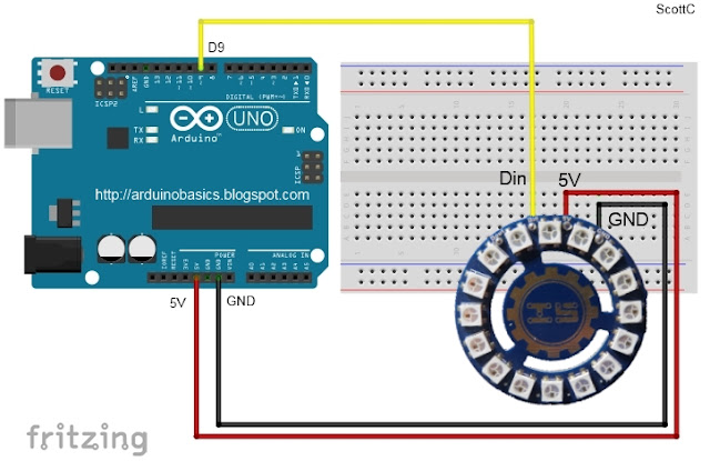
Connecting ONE LED Ring to the Arduino- (Click to enlarge)


  • 3 wires: You only need 3 wires to connect to the LED ring. If you only plan to light up a couple of LEDs at any one time this should be ok.
  • The SAFE WAY: A safer way to do this is to use an external power supply to power both the Arduino and the LED ring.
  • Electrolytic capacitor: By connecting a large 4700 uF 16V Electrolytic capacitor between the positive and negative terminals of power supply leads, with the negative leg of the capacitor attached to the negative terminal of the power supply, you will protect your LED rings from any initial onrush of current.


  • Protecting Resistor: It is also advisable to place a 300-400 ohm resistor between the Arduino's Digital Pin 9 (D9) and the LED Ring's Digital Input pin (Din). This protects the first LED from potential voltage spikes
  • Suitable wires: If you plan to chain a few of these LED rings together (see below), then you will probably want to keep the wires as short as possible and use a decent guage wire that can handle the current being drawn through them.


Connecting TWO LED Rings to the Arduino- (Click to enlarge)


  • Three extra wires:You only need 3 extra wires to connect an additional LED ring. A wire needs to connect the Digital output (Dout) of the first LED ring to the Digital Input (Din) of the 2nd LED ring.
  • Stay safe: Once again, a safer way to do this is to use an external power supply, a large electrolytic capacitor at the terminals, and a 300-400 ohm resistor between the Arduino and the first LED ring's digital input pin.


Connecting FOUR LED Ring to the Arduino- (Click to enlarge)


  • Sixty Four LEDs:You need 3 extra wires for each additional LED ring. 4 LED rings provides a total of 64 LEDs.
  • Watch the AMPS:At full brightness, this setup could potentially draw up to 4amps (or roughly 1 amp per LED ring)
  • External Supply essential: It is essential to use an external power supply to power these LEDs when there are so many of them. If you don't use an external power supply and you accidentally illuminate ALL of the LEDs, then you are likely to damage the microcontroller from excessive current draw.


Connection Tables

How to connect ONE LED Ring to the Arduino- (Click to enlarge)


How to connect TWO LED Rings to the Arduino- (Click to enlarge)


Concluding comments

In this tutorial I showed you how to go about decorating a Disco Ball cake and also showed you how to use the RGB LED rings from ICStation. If you look at the video you will see just how versatile these LED rings are. I would like to thank my wife for providing such an exciting project to work on, and ICStation for their collaborative efforts. Please make sure to share this project with all of your friends and family.


If you like this page, please do me a favour and show your appreciation :

 
Visit my ArduinoBasics Google + page.
Follow me on Twitter by looking for ScottC @ArduinoBasics.
I can also be found on Pinterest and Instagram.
Have a look at my videos on my YouTube channel.


Description: Arduino Disco Ball Cake Rating: 3.5 Reviewer: Unknown ItemReviewed: Arduino Disco Ball Cake
Get Arduino Data over the internet using jQuery and AJAX Reviewed by Unknown on 22:31 Rating: 4.5

Get Arduino Data over the internet using jQuery and AJAX

Description

Have you ever wanted to transmit Arduino data over the internet?

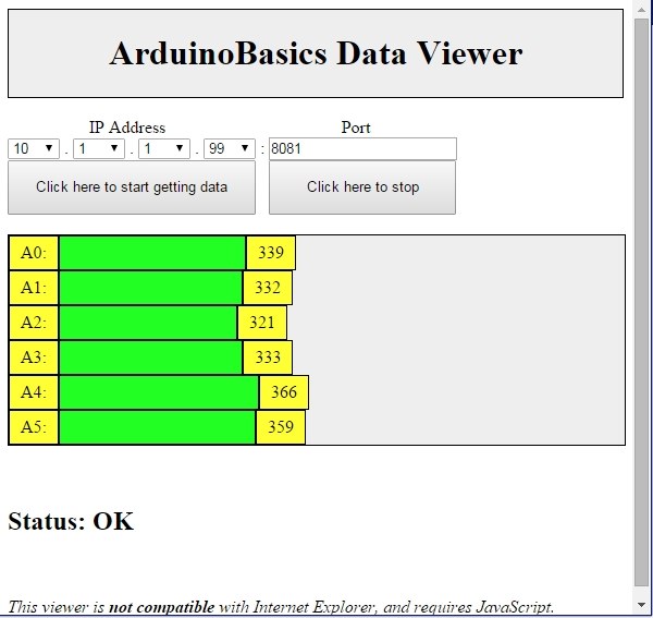
In this tutorial, we will design a web page that will retrieve Analog readings from the Arduino's Analog Pins and display them on a bar chart within the web page.

The web page will use jQuery and AJAX to request the data from the Arduino Web Server, allowing us to update the bar chart dynamically, without having to refresh the entire web page. The Arduino Web Server will send the Analog readings to the web page in JSON format where it will be processed and displayed accordingly.

In this tutorial, I will not have anything connected to the Arduino's Analog pins, which means the data retrieved will be that of randomly floating analog pins. Feel free to connect a potentiometer, temperature sensor or any other analog sensor to these pins if you want to create a more "useful" project.

The main aim here was to show you how to transmit the data in JSON format, and to update only a portion of the web page using asynchronous communication (using AJAX), to improve the performance of data retrieval and visualisation.


Parts Required:

Please note: The WIZnet ioShield-A ver1.1 actually comes with the WIZ550io board. So if you buy the ioShield-A, you will receive both boards. I have provided the link to the WIZ550io shield because you can buy that shield on its own. Regardless, you will need to use both boards for this tutorial.


Arduino Libraries and IDE

To program the Arduino you will need to download the Arduino IDE, and install the WIZnet Ethernet Library. The Arduino IDE version used in this tutorial was version 1.6.4.
You may want to read the WIZnet wiki information for each WIZnet shield before use.


ARDUINO CODE:

Full description of the Arduino code is included in the YouTube video above. Once you have set up your Arduino Web Server, you should be able to ping it. Look at this website, if you don't know how to use the windows ping feature.


Getting the Arduino Board onto the internet:

There isn't anything really to hook up for this project. You just have to align the pins for each board and stack them. You can power the Arduino via the USB cable. This will also be useful for debugging and printing to the Serial monitor. An ethernet cable needs to connect the WIZ550io board's ethernet port to your internet/network router

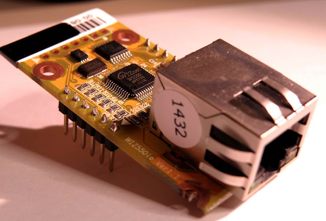
  • The WIZ550io board goes on the top
WIZ550io Shield

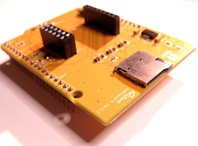
  • The ioShield-A is in the middle
WIZnet ioShield-A ver 1.1

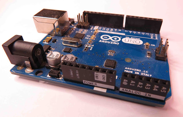
  • The Arduino UNO is on the bottom
Arduino UNO

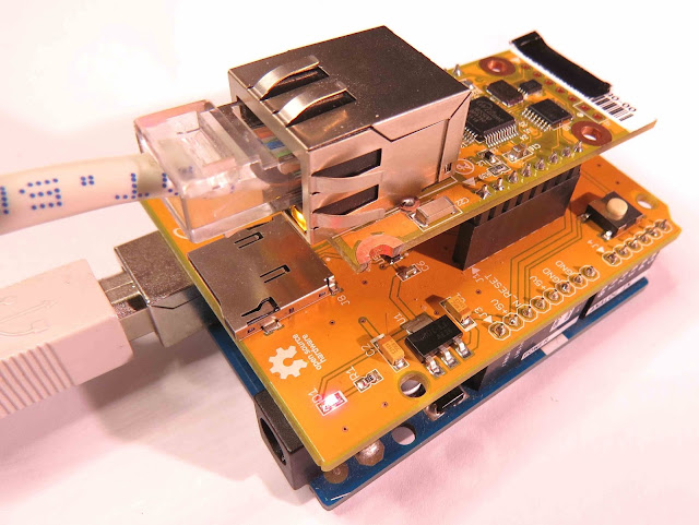
  • This is what it looks like when they are stacked together
Arduino UNO plus ioShield-A plus WIZ550io shield

  • If you want to gain easy access to the Analog or digital pins without de-soldering the ioShield-A, you can introduce some female headers like this:
Arduino UNO with some extra Female headers

  • Please note that the ioShield-A utilises a number of pins on the Arduino UNO - including: D2, D4, D7, D10, GND, and IOREF, RESET, 5V, GND, GND and ICSP pins
  • All Analog pins are available for use


Set the Arduino Web Server on your local network

You can test this project on your local network. You just have to choose an available IP address and PORT within your router's IP range. If you don't know your local IP address range - you can have a look at this site to give you a helping hand.


Set the Arduino Web Server to be accessed from anywhere in the world

If you want to access your Arduino from anywhere in the world, you need to set up Port Forwarding on your internet network router. The following useful guides will hopefully get you on the right track, if you have never set up Port forwarding.


In my case, I programmed the Arduino UNO Web Server to take the following ip address on my internal network: 10.1.1.99

I programmed the Arduino Web Server to listen for Web Browsers on port 8081.
So if I wanted to connect to the Arduino Web Server through my home network, I just had to type in this web address into my web browser: http://10.1.1.99:8081

If you plan to connect to the Arduino using port 80 (which is the default port for web browsers), you can just type the IP address without specifying the port (eg. http://10.1.1.99/ )

The web browser should display the Arduino data in JSON format (the YouTube video above will show you what that looks like).

Once I knew I could connect to the Arduino in my internal network, I then set up port forwarding on my router so that I could type in my external IP address and special port to tunnel my way into my Arduino Web Server on my internal network. This is what I had to do on my router, but you may need to do something different.

  1. My first step was to find out my public/external IP address by typing "what is my IP address" into google. If you want to know your external IP address click here.
  2. I then typed my router's ip address into a web browser, and logged into my router.
  3. I went to the advanced settings tab
  4. Selected "Port Forwarding" from the side menu
  5. Filled out all of the details on the first line of the Ports list
    • Enable box = ticked
    • Description = Arduino
    • WAN interface = pppoe_atm0/ppp0
    • Inbound port = 8082
    • Type = TCP
    • Private IP address = 10.1.1.99
    • Private port = 8081
  6. Saved the settings

Now that I had port forwarding enabled, I could type the ip address (that I obtained in step 1) into my browser and specified port 8082 (instead of 8081) - eg. http://190.11.70.253:8082/

And now I can access my Arduino Web server from anywhere in the world. I can even access it from my smart phone. Once again, this will only return the Analog data in JSON format.


The Web Page GUI

The Arduino is now on the internet, so there are two options. You can either

Instructions on how to use these web pages, are listed below the HTML code.


To retrieve data from your Arduino Web Server, please make sure that it is connected and visible from outside of you local network. You will need to have port forwarding enabled. Information on port forwarding is described above.

  1. Find what your external IP address is.
  2. Enter this address using the IP address drop-down boxes within the "ArduinoBasics Webserver Data viewer" web page
  3. Enter the port forwarding port number (eg. 8082) into the box labelled "Port"
  4. Then click on the "Click here to start getting data" button - you should start to see the bar charts moving and status should be OK
  5. If the bar charts do not move, and the status message says "Failed to get DATA!!" - then the web page was unable to connect to the Arduino for some reason.


ArduinoBasics Web Data Viewer Web Page Example

Troubleshooting

  • You may want to type in the web address into your web browser, to make sure that data is being retrieved.
  • You can also open the Serial monitor in the Arduino IDE to make sure that an IP address is being displayed
  • Ensure that you have enabled the port forwarding option on your router
  • Have a look at Developer Tools within Google Chrome to help diagnose web page related issues.
  • The web page will not work properly if you use Internet Explorer or if you have javascript disabled within your browser.

Concluding comments

This tutorial showed you how to connect to your Arduino UNO over the internet, and retrieve data in JSON format using jQuery and AJAX. The web page can be modified to suit your own needs, plus it would be more useful if the Arduino was actually monitoring something, rather than logging data from floating pins. It would also be useful if the Arduino could be controlled to blink an LED, or to turn a motor... but I will leave that project for another day. I hope you enjoyed this tutorial - if it helped you in any way, please consider donating a small "tip" into my money jar. Thank you.


If you like this page, please do me a favour and show your appreciation :

 
Visit my ArduinoBasics Google + page.
Follow me on Twitter by looking for ScottC @ArduinoBasics.
I can also be found on Pinterest and Instagram.
Have a look at my videos on my YouTube channel.


However, if you do not have a google profile...
Feel free to share this page with your friends in any way you see fit.


Description: Get Arduino Data over the internet using jQuery and AJAX Rating: 3.5 Reviewer: Unknown ItemReviewed: Get Arduino Data over the internet using jQuery and AJAX
Back to top