Long straight lines of LED luminescence is nice, but sometimes you may want to light up something that has an unusual shape, or is not so linear. This is where the 12mm diffused flat digital RGB LED Pixels can come into play. This cool strand of 25 RGB LED pixels fit nicely into 12mm pre-drilled holes of any material you like.
This tutorial is dedicated to making a LED Light Box. I wanted the box to be equally as interesting during the day as it was at night. If you decide you make your own, feel free to be as creative as you want !! However, if you lack artistic acumen, you may need to source a minion or two.
Before you start to hook up any components, upload the following sketch to the Arduino microcontroller. I am assuming that you already have the Arduino IDE installed on your computer. If not, the IDE can be downloaded from here.
The FastLED library is useful for simplifying the code for programming the RGB LED pixels. The latest "FastLED library" can be downloaded from here. I used FastLED library version 3.0.3 in this project.
If you have a different LED strip or your RGB LED pixels have a different chipset, make sure to change the relevant lines of code to accomodate your hardware. I would suggest you try out a few of the FastLED library examples before using the code below, so that you become more familiar with the library, and will be better equipped to make the necessary changes.
If you have a single strand of 25 RGB LED pixels with the WS8201 chipset, then you will not have to make any modification below.
ARDUINO CODE:
Arduino Code Description
The code above will generate a randomised raindrop pattern on the Arduino LED Light box, however I have written code for a few more LED animations. These animations were written specifically for this light-box setup. In other words, once you have hooked everything up, you will be able to upload these other LED animations to the Arduino board without any further modification to the hardware/wiring, and yet experience a totally different light effect. You can find the code for the other animation effects by clicking on the links below:
Each LED pixel can draw up to 60 milliamps at maximum brightness (white). ie. 20 mA for each colour (red, green and blue). Therefore you should not try to power the LED strand directly from the Arduino, because the strand will draw too much current and damage the microcontroller(and possibly your USB port too). The LED strand will therefore need to be powered by a separate power supply. The power supply must supply the correct voltage (5V DC) and must also be able to supply sufficient current (1.5A or greater per strand of 25 LEDs).
Excessive voltage will damage or destroy your LED pixel strand. The LEDs will only draw as much current as they need, however your power supply must provide at least 1.5A or greater for each strand. If you chain two strands together, you will need a 5V 3A power supply.
RGB LED pixel strand connection
There are 25 LED pixels per strand. Four of the wires at each end of the strand are terminated with a JST connector. The red wire is for power (VCC), blue wire for ground (GND), yellow wire is for Data, and green wire for Clock. A spare red wire (VCC) and a spare blue wire (GND) are attached to the ends of each strand for convenience, however, I did not use either. Please double check the colour of your wires... they may be different.
If you want to attach the LED strand to a breadboard, you can cut the JST connector off and use the LED pixel strand wires. Alternatively, if you would prefer to preserve the JST connector, you can simply insert jumper wires (or some male header pins) into the JST connector, and then plug them into the breadboard as required.
Each LED pixel is individually controllable using two pins on your Arduino. The strand is directional. i.e. There is an INPUT side and an OUTPUT side. The strand should be connected such that wires from the microcontroller are attached to the INPUT side of the first LED pixel. The arrows on each LED show the direction of data flow from INPUT to OUTPUT. The arrow on the first LED pixel should be pointing towards the second LED pixel, NOT towards the breadboard.
Other considerations
As a precaution, you should use a large capacitor across the + and - terminals of the power supply to prevent the initial onrush of current from damaging the RGB LED pixels. I used a 4700uF 16V Electrolytic capacitor for this purpose. According to Adafruit, a 1000uF 6.3V capacitor (or higher) will also do the trick. You may also want to consider a 330 ohm resistor between the Arduino Digital pin and the strand's DATA pin.
If you want to power the Arduino using the regulated 5V external power supply. Disconnect the USB cable from the Arduino, and then connect the positive terminal of the power supply to the 5V pin on the Arduino. Be warned however, that excess voltage at this pin could damage your Arduino, because the 5V regulator will be bypassed.
Providing the USB cable is NOT connected to the Arduino, it should now be safe to plug the power supply into the wall. This setup will allow you to power the RGB LED pixel strand and the Arduino using the same power supply.
WARNING: Never change any connections while the circuit is powered.
For more information about these RGB LED pixel strands, you may want to visit the Adafruit site. Adafruit was the source for most of these RGB LED pixel Strand precautions.
Fritzing diagram
The following diagram demonstrates how to connect the RGB LED pixel Strand to the Arduino and to the External 5V power supply.
These instructions will help to guide you through the process of connecting your RGB LED pixel strand to the Arduino, and to the external power supply. The instructions assume that you will be powering the Arduino via a USB cable.
LightBox assembly
You will need to drill a 12mm hole into the craft timber box for each LED on the strand. It is worth taking the time to make accurate measurements before drilling the holes.
I made 12 holes for the outside circle pattern (12cm diameter), 6 holes for the inside circle pattern (8cm diameter), and a hole in the centre. I also made two holes at the front of the box, two on the left side, and two on the right side. I made one last hole at the back of the box for the 2.1mm DC power line socket.
Therefore you should have a total of 26 holes in the box. 25 of the holes are for the RGB LED pixel LEDs and one for the external power supply socket.
The lid of the box is about 19.5cm x 14.5cm long, which makes for a very tight squeeze. Probably too tight, because you have to account for the inner dimensions of the box. The inside of the box is used to house the Arduino, breadboard, the chipset side of the LEDs and cables/components. The inner dimensions of the box are 18cm x 13cm. Therefore, the housing for the LED chipset PCB (1.8cm x 2.5cm) prevented the box from closing. I used a Dremel to carve out the space required to close the lid.
Each LED is approximately 8cm apart on the strand, however, if you are really keen, you could cut the wires and extend them to any distance you require. But keep in mind that each LED is mounted on a small PCB (with a WS2801 chipset).You will therefore need to leave a minimum of 2cm between each 12mm hole to accomodate the size of the PCB+LED. If you plan carefully, you can probably squeeze a couple of LEDs within a distance of 1cm... but I would recommend that you give yourself a bit more room, because the PCBs are not square, and there is a good chance that you will have to start all over again.
In hindsight, I could have made the circle patterns a bit smaller, however I don't know if I could have packed these LEDs any closer. The diameter of the inner circle pattern must be at least 2cm smaller than the outer circle pattern. So I think "a bigger box" would have been the best option.
Once all of the holes have been drilled, paint and decorate the box to suit your style.
When the paint is dry, insert the LEDs into the drilled holes in number order. You can see the end result below.
Project Pictures
These pictures show the Light box after it has been drilled and painted. The LEDs have been inserted into their respective holes, and all wires + Arduino + breadboard are hidden within the box.
Concluding comments
Once you start writing LED animations for the RGB LED pixel Lightbox, it is very hard to stop. The colour combinations
If you like this page, please do me a favour and show your appreciation :
We will be using an MT8870 DTMF module with an Arduino UNO to control a small servo motor in this project. The DTMF module gives the Arduino super-powers and allows you to control the Servo motor in so many ways. For example, this tutorial will show you how to control the servo motor using:
a YouTube Video
a voice recorder
A web application (Online tone generator)
A smart phone app (DTMF Pad)
A touch-tone phone to cell-phone call
All of these control methods will take advantage of the same exact Arduino code/sketch. But how??? The MT8870 DTMF decoder is quite a neat little module that allows you incorporate DTMF technology into your arduino projects. DTMF stands for Dual-Tone Multi-Frequency. DTMF tones are commonly associated with touch-tone phones and other telecommunication systems. When you press the number "1" on a touch-tone phone, two sine waves with frequencies: 697Hz and 1209Hz are combined to produce a unique DTMF signal which can be transmitted through the phone line. The MT8870 DTMF module can take this signal as an input, and decode it to produce a binary output.
The DTMF module does not care how you produce the DTMF tone. However, if it receives this tone, it will decode it. We can take advantage of this feature to supply the module with tones from different sources. The module has a 3.5mm port for line input. Providing you can connect your DTMF source to this line input in some way, it should work. I must warn you, however that this is a line input and NOT a microphone input. If you wanted to use a microphone, you will need to boost or amplify the signal before sending it to the DTMF module.
You will need the following parts for this project
/* ================================================================================================================================================== Project: MT8870 DTMF Servo sketch Author: Scott C Created: 4th August 2015 Arduino IDE: 1.6.4 Website: http://arduinobasics.blogspot.com/p/arduino-basics-projects-page.html Description: This project will allow you to control a Servo motor using an Arduino UNO and a MT8870 DTMF Module. The DTMF signal is received through the 3.5mm port of the DTMF module and is decoded. We will use the decoded output to control the position of the Servo. A SG-5010 Servo motor was used in this project. ===================================================================================================================================================== *///This sketch uses the Servo library that comes with the Arduino IDE #include <Servo.h> //Global variables----------------------------------------------------------------------------------------- ServoSG5010;// The SG5010 variable provides Servo functionality intservoPosition=0;// The servoPosition variable will be used to set the position of the servo byteDTMFread;// The DTMFread variable will be used to interpret the output of the DTMF module. constintSTQ=3;// Attach DTMF Module STQ Pin to Arduino Digital Pin 3 constintQ4=4;// Attach DTMF Module Q4 Pin to Arduino Digital Pin 4 constintQ3=5;// Attach DTMF Module Q3 Pin to Arduino Digital Pin 5 constintQ2=6;// Attach DTMF Module Q2 Pin to Arduino Digital Pin 6 constintQ1=7;// Attach DTMF Module Q1 Pin to Arduino Digital Pin 7 /*========================================================================================================= setup() : will setup the Servo, and prepare the Arduino to receive the MT8700 DTMF module's output. ========================================================================================================== */voidsetup(){SG5010.attach(9);// The Servo signal cable will be attached to Arduino Digital Pin 9 SG5010.write(servoPosition);// Set the servo position to zero. //Setup the INPUT pins on the Arduino pinMode(STQ,INPUT);pinMode(Q4,INPUT);pinMode(Q3,INPUT);pinMode(Q2,INPUT);pinMode(Q1,INPUT);}/*========================================================================================================= loop() : Arduino will interpret the DTMF module output and position the Servo accordingly ========================================================================================================== */voidloop(){if(digitalRead(STQ)==HIGH){//When a DTMF tone is detected, STQ will read HIGH for the duration of the tone. DTMFread=0;if(digitalRead(Q1)==HIGH){//If Q1 reads HIGH, then add 1 to the DTMFread variable DTMFread=DTMFread+1;}if(digitalRead(Q2)==HIGH){//If Q2 reads HIGH, then add 2 to the DTMFread variable DTMFread=DTMFread+2;}if(digitalRead(Q3)==HIGH){//If Q3 reads HIGH, then add 4 to the DTMFread variable DTMFread=DTMFread+4;}if(digitalRead(Q4)==HIGH){//If Q4 reads HIGH, then add 8 to the DTMFread variable DTMFread=DTMFread+8;}servoPosition=DTMFread*8.5;//Set the servoPosition varaible to the combined total of all the Q1 to Q4 readings. Multiply by 8.5 to amplify the servo rotation. }SG5010.write(servoPosition);//Set the servo's position according to the "servoPosition" variable. }
Fritzing Sketch
Connect the Arduino to the MT8870 DTMF module, and to a Servo. Use the following Fritzing sketch as a guide.
(Click the image above to enlarge it)
Discussion
You will need to connect a cable from the DTMF module's 3.5mm port to that of your smart phone, computer, voice recorder or any other DTMF source of your choice.
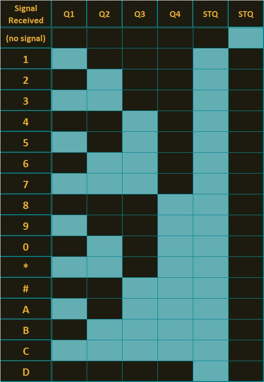
When you power up your Arduino, the Servo motor should turn all the way to the left to it's zero position. Once the DTMF module receives a DTMF signal, it will identify the relevant frequecies as described in the table at the beginning of this tutorial, and produce a binary like output. You will notice the DTMF module's onboard LEDs light up when a tone is detected. Onboard LED (D5) will turn on for the length of the DTMF tone it just received, and turn off when the tone has stopped. On the other hand, the onboard LEDs (D1 to D4) will light up depending on the tone received, and will remain lit until the module receives another tone. The onboard LEDs are a visual representation of the voltages applied to the DTMF module's pins (Q1 to Q4, and STQ). Q1 matches D1, Q2 matches D2 etc etc. and STQ matches D5.
You will notice that there are two STQ pins on the DTMF module. The STQ pin that is closest to Q4 will only go high when a DTMF tone is detected, and will remain high for the duration of the tone. The other STQ pin is the exact opposite. It will switch LOW when a tone is received and remain LOW for the duration of the tone. When there is no tone, this STQ pin will remain HIGH. The table below provides a summary of the DTMF module outputs, with a blue box representing a voltage applied to that pin (HIGH), whereas a black box indicates no voltage applied (LOW).
In order to follow this project, you need a source of DTMF tones. You can produce DTMF tones using a touch-tone phone, or through the use of a DTMF Pad app. If you are feeling creative, you can create a DTMF song/tune like the one I posted on YouTube. You can see the video below:
As you can see from the video, I also recorded the DTMF tune onto a voice recorder, and was able to control the servo that way. If you are not feeling creative, you can visit this website to create DTMF tones from your browser.
Concluding comments
This project was very fun, and shows some novel ways to control your Arduino. After completing the project, I realised that I could use this module to alert me when new emails or messages arrive on my phone or computer. If you have the ability to change the email or message notification sound to a DTMF tone, you should be able to get the module and Arduino to respond accordingly. Oh well, maybe I'll save that project for another day.
If this project helped you in anyway or if you use my code within your project, please let me know in the comments below. I would be interested to see what you did.
If you like this page, please do me a favour and show your appreciation :
However, if you do not have a google profile... Feel free to share this page with your friends in any way you see fit.
Description: MT8870 DTMF - Dual Tone Multi Frequency Decoder
Rating: 3.5
Reviewer: Unknown
ItemReviewed: MT8870 DTMF - Dual Tone Multi Frequency Decoder
NeoPixel Heart Beat Display
Reviewed by Unknown on
01:11
Rating: 4.5
In this project, your heart will control a mesmerising LED sequence on a 5 metre Neopixel LED strip with a ws2812B chipset. Every heart beat will trigger a LED animation that will keep you captivated and attached to your Arduino for ages. The good thing about this project is that it is relatively easy to set up, and requires no soldering. The hardest part is downloading and installing the FastLED library into the Arduino IDE, but that in itself is not too difficult. The inspiration and idea behind this project came from Ali Murtaza, who wanted to know how to get an LED strip to pulse to his heart beat.
Have a look at the video below to see this project in action.
Before you start any LED strip project, the first thing you will need to think about is POWER. According to the Adafruit website, each individual NeoPixel LED can draw up to 60 milliamps at maximum brightness - white. Therefore the amount of current required for the entire strip will be way more than your Arduino can handle. If you try to power this LED strip directly from your Arduino, you run the risk of damaging not only your Arduino, but your USB port as well. The Arduino will be used to control the LED strip, but the LED strip will need to be powered by a separate power supply. The power supply you choose to use is important. It must provide the correct voltage, and must able to supply sufficient current.
Operating Voltage (5V)
The operating voltage of the NeoPixel strip is 5 volts DC. Excessive voltage will damage/destroy your NeoPixels.
Current requirements (9.0 Amps)
OpenLab recommend the use of a 5V 10A power supply. Having more Amps is OK, providing the output voltage is 5V DC. The LEDs will only draw as much current as they need. To calculate the amount of current this 5m strip can draw with all LEDs turned on at full brightness - white:
30 NeoPixel LEDs x 60mA x 5m = 9000mA = 9.0 Amps for a 5 metre strip.
Therefore a 5V 10A power supply would be able to handle the maximum current (9.0 Amps) demanded by a 5m NeoPixel strip containing a total of 150 LEDs.
Arduino Libraries and IDE
Before you start to hook up any components, upload the following sketch to the Arduino microcontroller. I am assuming that you already have the Arduino IDE installed on your computer. If not, the IDE can be downloaded from here.
The FastLED library is useful for simplifying the code for programming the NeoPixels. The latest "FastLED library" can be downloaded from here. I used FastLED library version 3.0.3 in this project.
If you have a different LED strip or your NeoPixels have a different chipset, make sure to change the relevant lines of code to accomodate your hardware. I would suggest you try out a few of the FastLED library examples before using the code below, so that you become more familiar with the library, and will be better equipped to make the necessary changes. If you have a 5 metre length of the NeoPixel 30 LED/m strip with the ws2812B chipset, then you will not have to make any modification below.
/* ================================================================================================ Project: NeoPixel Heart Beat Display Neopixel chipset: ws2812B (30 LED/m strip) Author: Scott C Created: 8th July 2015 Arduino IDE: 1.6.4 Website: http://arduinobasics.blogspot.com/p/arduino-basics-projects-page.html Description: This sketch will display a heart beat on a 5m Neopixel LED strip. Requires a Grove Ear-clip heart rate sensor and a Neopixel strip. This project makes use of the FastLED library: http://fastled.io/ You may need to modify the code below to accomodate your specific LED strip. See the FastLED library site for more details. ================================================================================================== *///This project needs the FastLED library - link in the description. #include "FastLED.h" //The total number of LEDs being used is 150 #define NUM_LEDS 150 // The data pin for the NeoPixel strip is connected to digital Pin 6 on the Arduino #define DATA_PIN 6 //Attach the Grove Ear-clip heart rate sensor to digital pin 2 on the Arduino. #define EAR_CLIP 2 //Initialise the LED array CRGBleds[NUM_LEDS];//Initialise the global variables used to control the LED animation intledNum=0;//Keep track of the LEDs booleanbeated=false;//Used to identify when the heart has beated intrandomR=0;//randomR used to randomise the fade-out of the LEDs //================================================================================================ // setup() : Is used to initialise the LED strip //================================================================================================ voidsetup(){FastLED.addLeds<NEOPIXEL,DATA_PIN>(leds,NUM_LEDS);//Set digital pin 2 (Ear-clip heart rate sensor) as an INPUT pinMode(EAR_CLIP,INPUT);}//================================================================================================ // loop() : Take readings from the Ear-clip sensor, and display the animation on the LED strip //================================================================================================ voidloop(){//If the Ear-clip sensor moves from LOW to HIGH, call the beatTriggered method if(digitalRead(EAR_CLIP)>0){//beatTriggered() is only called if the 'beated' variable is false. //This prevents multiple triggers from the same beat. if(!beated){beatTriggered();}}else{beated=false;//Change the 'beated' variable to false when the Ear-clip heart rate sensor is reading LOW. }//Fade the LEDs by 1 unit/cycle, when the heart is at 'rest' (i.e. between beats) fadeLEDs(5);}//================================================================================================ // beatTriggered() : This is the LED animation sequence when the heart beats //================================================================================================ voidbeatTriggered(){//Ignite 30 LEDs with a red value between 0 to 255 for(inti=0;i<30;i++){//The red channel is randomised to a value between 0 to 255 leds[ledNum].r=random8();FastLED.show();//Call the fadeLEDs method after every 3rd LED is lit. if(ledNum%3==0){fadeLEDs(5);}//Move to the next LED ledNum++;//Make sure to move back to the beginning if the animation falls off the end of the strip if(ledNum>(NUM_LEDS-1)){ledNum=0;}}//Ignite 20 LEDS with a blue value between 0 to 120 for(inti=0;i<20;i++){//The blue channel is randomised to a value between 0 to 120 leds[ledNum].b=random8(120);FastLED.show();//Call the fadeLEDs method after every 3rd LED is lit. if(ledNum%3==0){fadeLEDs(5);}//Move to the next LED ledNum++;//Make sure to move back to the beginning if the animation falls off the end of the strip if(ledNum>(NUM_LEDS-1)){ledNum=0;}}//Change the 'beated' variable to true, until the Ear-Clip sensor reads LOW. beated=true;}//================================================================================================ // fadeLEDs() : The fading effect of the LEDs when the Heart is resting (Ear-clip reads LOW) //================================================================================================ voidfadeLEDs(intfadeVal){for(inti=0;i<NUM_LEDS;i++){//Fade every LED by the fadeVal amount leds[i].fadeToBlackBy(fadeVal);//Randomly re-fuel some of the LEDs that are currently lit (1% chance per cycle) //This enhances the twinkling effect. if(leds[i].r>10){randomR=random8(100);if(randomR<1){//Set the red channel to a value of 80 leds[i].r=80;//Increase the green channel to 20 - to add to the effect leds[i].g=20;}}}FastLED.show();}
NeoPixel Strip connection
The NeoPixel strip is rolled up when you first get it. You will notice that there are wires on both sides of the strip. This allows you to chain LED strips together to make longer strips. The more LEDs you have, the more current you will need. Connect your Arduino and power supply to the left side of the strip, with the arrows pointing to the right. (i.e. the side with the "female" jst connector).
NeoPixel Strip Wires
There are 5 wires that come pre-attached to either side of the LED strip.
You don't have to use ALL FIVE wires, however you will need at least one of each colour: red, white & green.
Fritzing sketch
The following diagram will show you how to wire everything together
(click to enlarge)
Arduino Power considerations
Please note that the Arduino is powered by a USB cable. If you plan to power the Arduino from your power supply, you will need to disconnect the USB cable from the Arduino FIRST, then connect a wire from the 5V line on the Power supply to the 5V pin on the Arduino. Do NOT connect the USB cable to the Arduino while the 5V wire is connected to the Arduino.
Large Capacitor
Adafruit also recommend the use of a large capacitor across the + and - terminals of the LED strip to "prevent the initial onrush of current from damaging the pixels". Adafruit recommends a capacitor that is 1000uF, 6.3V or higher. I used a 4700uF 16V Electrolytic Capacitor.
Resistor on Data Pin
Another recommendation from Adafruit is to place a "300 to 500 Ohm resistor" between the Arduino's data pin and the data input on the first NeoPixel to prevent voltage spikes that can damage the first pixel. I used a 330 Ohm resistor.
Grove Ear-clip heart rate sensor connection
The Grove Base shield makes it easy to connect Grove modules to the Arduino. If you have a Grove Base shield, you will need to connect the Ear-clip heart rate sensor to Digital pin 2 as per the diagram below.
Completed construction
Once you have everything connected, you can plug the USB cable into the Arduino, and turn on the LED power supply. Attach the ear-clip to your ear (or to your finger) and allow a few seconds to allow the sensor to register your pulse. The LED strip will light up with every heart beat with an animation that moves from one end of the strip to the other in just three heart beats. When the ear-clip is not connected to your ear or finger, the LEDs should remain off. However, the ear clip may "trigger" a heart beat when opening or closing the clip.
Here is a picture of all the components (fully assembled).
Concluding comments
This very affordable LED strip allows you to create amazing animations over a greater distance. I thought that having less LEDs per metre would make the animations look "jittery", but I was wrong, they look amazing. One of the good things about this strip is the amount of space between each Neopixel, allowing you to easily cut and join the strip to the size and shape you need.
This LED strip is compatible with the FastLED library, which makes for easy LED animation programming. While I used this LED strip to display my heart beat, you could just as easily use it to display the output of any other sensor attached to the Arduino.
If you like this page, please do me a favour and show your appreciation :
The NeoPixel Digital RGB LED Strip (144 LED/m) is a really impressive product that will have you lighting up your room in next to no time. The 144 individually addressable LEDs packed onto a 1 metre flexible water resistant strip, enables a world of luminescent creativity that will blow your blinking Arduino friends away. The following tutorial will show you how to create an immersive and interactive LED display using an Arduino UNO, a potentiometer and an accelerometer. There will be a total of FIVE LED sequences to keep you entertained or you can create your own !
Before you start any LED strip project, the first thing you will need to think about is POWER. According to the Adafruit website, each individual NeoPixel LED can draw up to 60 milliamps at maximum brightness - white. Therefore the amount of current required for the entire strip will be way more than your Arduino can handle. If you try to power this LED strip directly from your Arduino, you run the risk of damaging not only your Arduino, but your USB port as well. The Arduino will be used to control the LED strip, but the LED strip will need to be powered by a separate power supply. The power supply you choose to use is important. It must provide the correct voltage, and must able to supply sufficient current.
Operating Voltage(5V)
The operating voltage of the NeoPixel strip is 5 volts DC. Excessive voltage will damage/destroy your NeoPixels.
Current requirements (8.6 Amps)
OpenLab recommend the use of a 5V 10A power supply. Having more Amps is OK, providing the output voltage is 5V DC. The LEDs will only draw as much current as they need. To calculate the amount of current this 1m strip can draw with all LEDs turned on at full brightness - white:
144 NeoPixel LEDs x 60 mA x 1 m = 8640 mA = 8.64 Amps for a 1 metre strip.
Therefore a 5V 10A power supply would be able to handle the maximum current (8.6 Amps) demanded by a single 1m NeoPixel strip of 144 LEDs.
Arduino Libraries and IDE
Before you start to hook up any components, upload the following sketch to the Arduino microcontroller. I am assuming that you already have the Arduino IDE installed on your computer. If not, the IDE can be downloaded from here.
The FastLED library is useful for simplifying the code for programming the NeoPixels. The latest "FastLED library" can be downloaded from here. I used FastLED library version 3.0.3 in this project.
If you have a different LED strip or your NeoPixels have a different chipset, make sure to change the relevant lines of code to accomodate your hardware. I would suggest you try out a few of the FastLED library examples before using the code below, so that you become more familiar with the library, and will be better equipped to make the necessary changes. If you have a single 144 NeoPixel LED/m strip with the ws2812B chipset, then you will not have to make any modifications below (unless you want to).
/* ================================================================================================================================================== Project: NeoPixel Playground Neopixel chipset: ws2812B (144 LED/m strip) Author: Scott C Created: 12th June 2015 Arduino IDE: 1.6.4 Website: http://arduinobasics.blogspot.com/p/arduino-basics-projects-page.html Description: This project will allow you to cycle through and control five LED animation sequences using a potentiometer and an accelerometer Sequence 1: Cylon with Hue Control Control: Potentiometer only Sequence 2: Cylon with Brightness Control Control: Potentiometer only Sequence 3: Comet effect with Hue and direction control Control: Potentiometer and Accelerometer (Y axis only) Sequence 4: FireStarter / Rainbow effect with Hue and Direction control Control: Potentiometer and Accelerometer (Y axis only) Sequence 5: Digital Spirit Level Control: Accelerometer only (Y axis) This project makes use of the FastLED library. Some of the code below was adapted from the FastLED library examples (eg. Cylon routine). The Comet, FireStarter and Digital Spirit Level sequence was designed by ScottC. The FastLED library can be found here: http://fastled.io/ You may need to modify the code below to accomodate your specific LED strip. See the FastLED library site for more details. ===================================================================================================================================================== */
//This project needs the FastLED library - link in the description. #include "FastLED.h"
//The total number of LEDs being used is 144 #define NUM_LEDS 144
// The data pin for the NeoPixel strip is connected to digital Pin 6 on the Arduino #define DATA_PIN 6
//Initialise the LED array, the LED Hue (ledh) array, and the LED Brightness (ledb) array. CRGB leds[NUM_LEDS]; byte ledh[NUM_LEDS]; byte ledb[NUM_LEDS];
//Pin connections constint potPin = A0; // The potentiometer signal pin is connected to Arduino's Analog Pin 0 constint yPin = A4; // Y pin on accelerometer is connected to Arduino's Analog Pin 4 // The accelerometer's X Pin and the Z Pin were not used in this sketch
//Global Variables --------------------------------------------------------------------------------- byte potVal; // potVal: stores the potentiometer signal value byte prevPotVal=0; // prevPotVal: stores the previous potentiometer value int LEDSpeed=1; // LEDSpeed: stores the "speed" of the LED animation sequence int maxLEDSpeed = 50; // maxLEDSpeed: identifies the maximum speed of the LED animation sequence int LEDAccel=0; // LEDAccel: stores the acceleration value of the LED animation sequence (to speed it up or slow it down) int LEDPosition=72; // LEDPosition: identifies the LED within the strip to modify (leading LED). The number will be between 0-143. (Zero to NUM_LEDS-1) int oldPos=0; // oldPos: holds the previous position of the leading LED byte hue = 0; // hue: stores the leading LED's hue value byte intensity = 150; // intensity: the default brightness of the leading LED byte bright = 80; // bright: this variable is used to modify the brightness of the trailing LEDs int animationDelay = 0; // animationDelay: is used in the animation Speed calculation. The greater the animationDelay, the slower the LED sequence. int effect = 0; // effect: is used to differentiate and select one out of the four effects int sparkTest = 0; // sparkTest: variable used in the "sparkle" LED animation sequence boolean constSpeed = false; // constSpeed: toggle between constant and variable speed.
//=================================================================================================================================================== // setup() : Is used to initialise the LED strip //=================================================================================================================================================== voidsetup() { delay(2000); //Delay for two seconds to power the LEDS before starting the data signal on the Arduino FastLED.addLeds<WS2812B, DATA_PIN, GRB>(leds, NUM_LEDS); //initialise the LED strip }
//=================================================================================================================================================== // loop() : The Arduino will take readings from the potentiometer and accelerometer to control the LED strip //=================================================================================================================================================== voidloop(){ readPotentiometer(); adjustSpeed(); constrainLEDs();
switch(effect){ case 0: // 1st effect : Cylon with Hue control - using Potentiometer cylonWithHueControl(); break;
case 1: // 2nd effect : Cylon with Brightness control - using Potentiometer cylonWithBrightnessControl(); break;
case 2: // 3rd effect : Comet effect. Hue controlled by potentiometer, direction by accelerometer cometEffect(); break;
case 3: // 4th effect : FireStarter / Rainbow Sparkle effect. Direction controlled by accelerometer, sparkle by potentiometer. fireStarter(); break;
case 4: levelSense(); // 5th effect : LevelSense - uses the accelerometer to create a digital "spirit" level. break; } }
//=================================================================================================================================================== // readPotentiometer() : Take a potentiometer reading. This value will be used to control various LED animations, and to choose the animation sequence to display. //=================================================================================================================================================== void readPotentiometer(){ //Take a reading from the potentiometer and convert the value into a number between 0 and 255 potVal = map(analogRead(potPin), 0, 1023 , 0, 255);
// If the potentiometer reading is equal to zero, then move to the next effect in the list. if(potVal==0){ if(prevPotVal>0){ // This allows us to switch effects only when the potentiometer reading has changed to zero (from a positive number). Multiple zero readings will be ignored. prevPotVal = 0; // Set the prev pot value to zero in order to ignore replicate zero readings. effect++; // Go to the next effect. if(effect>4){ effect=0; // Go back to the first effect after the fifth effect. } } } prevPotVal=potVal; // Keep track of the previous potentiometer reading }
//=================================================================================================================================================== // adjustSpeed() : use the Y axis value of the accelerometer to adjust the speed and the direction of the LED animation sequence //=================================================================================================================================================== void adjustSpeed(){ // Take a reading from the Y Pin of the accelerometer and adjust the value so that // positive numbers move in one direction, and negative numbers move in the opposite diraction. // We use the map function to convert the accelerometer readings, and the constrain function to ensure that it stays within the desired limits // The values of 230 and 640 were determined by trial and error and are specific to my accelerometer. You will need to adjust these numbers to suit your module.
// If the constSpeed variable is "true", then make sure that the speed of the animation is constant by modifying the LEDSpeed and LEDAccel variables. if(constSpeed){ LEDAccel=0; if(LEDSpeed>0){ LEDSpeed = maxLEDSpeed/1.1; // Adjust the LEDSpeed to half the maximum speed in the positive direction } if (LEDSpeed<0){ LEDSpeed = -maxLEDSpeed/1.1; // Adjust the LEDSpeed to half the maximum speed in the negative direction } }
// The Speed of the LED animation sequence can increase (accelerate), decrease (decelerate) or stay the same (constant speed) LEDSpeed = LEDSpeed + LEDAccel;
//The following lines of code are used to control the direction of the LED animation sequence, and limit the speed of that animation. if (LEDSpeed>0){ LEDPosition++; // Illuminate the LED in the Next position if (LEDSpeed>maxLEDSpeed){ LEDSpeed=maxLEDSpeed; // Ensure that the speed does not go beyond the maximum speed in the positive direction } }
if (LEDSpeed<0){ LEDPosition--; // Illuminate the LED in the Prior position if (LEDSpeed<-maxLEDSpeed){ LEDSpeed = -maxLEDSpeed; // Ensure that the speed does not go beyond the maximum speed in the negative direction } } }
//=================================================================================================================================================== // constrainLEDs() : This ensures that the LED animation sequence remains within the boundaries of the various arrays (and the LED strip) // and it also creates a "bouncing" effect at both ends of the LED strip. //=================================================================================================================================================== void constrainLEDs(){ LEDPosition = constrain(LEDPosition, 0, NUM_LEDS-1); // Make sure that the LEDs stay within the boundaries of the LED strip if(LEDPosition == 0 || LEDPosition == NUM_LEDS-1) { LEDSpeed = (LEDSpeed * -0.9); // Reverse the direction of movement when LED gets to end of strip. This creates a bouncing ball effect. } }
//=================================================================================================================================================== // cylonWithHueControl() : This is the 1st LED effect. The cylon colour is controlled by the potentiometer. The speed is constant. //=================================================================================================================================================== void cylonWithHueControl(){ constSpeed = true; // Make the LED animation speed constant showLED(LEDPosition, potVal, 255, intensity); // Illuminate the LED fadeLEDs(8); // Fade LEDs by a value of 8. Higher numbers will create a shorter tail. setDelay(LEDSpeed); // The LEDSpeed is constant, so the delay is constant }
//=================================================================================================================================================== // cylonWithBrightnessControl() : This is the 2nd LED effect. The cylon colour is red (hue=0), and the brightness is controlled by the potentiometer //=================================================================================================================================================== void cylonWithBrightnessControl(){ constSpeed = true; // Make speed constant showLED(LEDPosition, 0, 255, potVal); // Brightness is controlled by potentiometer. fadeLEDs(16); // Fade LEDs by a value of 16 setDelay(LEDSpeed); // The LEDSpeed is constant, so the delay is constant }
//=================================================================================================================================================== // cometEffect() : This is the 3rd LED effect. The random brightness of the trailing LEDs produces an interesting comet-like effect. //=================================================================================================================================================== void cometEffect(){ constSpeed = false; // The speed will be controlled by the slope of the accelerometer (y-Axis) showLED(LEDPosition, potVal, 255, intensity); // Hue will change with potentiometer.
//The following lines create the comet effect bright = random(50, 100); // Randomly select a brightness between 50 and 100 leds[LEDPosition] = CHSV((potVal+40),255, bright); // The trailing LEDs will have a different hue to the leading LED, and will have a random brightness fadeLEDs(8); // This will affect the length of the Trailing LEDs setDelay(LEDSpeed); // The LEDSpeed will be affected by the slope of the Accelerometer's y-Axis }
//=================================================================================================================================================== // fireStarter() : This is the 4th LED effect. It starts off looking like a ball of fire, leaving a trail of little fires. But as you // turn the potentiometer, it becomes more like a shooting star with a rainbow-sparkle trail. //=================================================================================================================================================== void fireStarter(){ constSpeed = false; // The speed will be controlled by the slope of the accelerometer (y-Axis) ledh[LEDPosition] = potVal; // Hue is controlled by potentiometer showLED(LEDPosition, ledh[LEDPosition], 255, intensity);
//The following lines create the fire starter effect bright = random(50, 100); // Randomly select a brightness between 50 and 100 ledb[LEDPosition] = bright; // Assign this random brightness value to the trailing LEDs sparkle(potVal/5); // Call the sparkle routine to create that sparkling effect. The potentiometer controls the difference in hue from LED to LED. fadeLEDs(1); // A low number creates a longer tail setDelay(LEDSpeed); // The LEDSpeed will be affected by the slope of the Accelerometer's y-Axis }
//=================================================================================================================================================== // levelSense() : This is the 5th and final LED effect. The accelerometer is used in conjunction with the LED strip to create a digital "Spirit" Level. // You can use the illuminated LEDs to identify the angle of the LED strip //=================================================================================================================================================== void levelSense(){ constSpeed = true; LEDPosition = constrain(map(analogRead(yPin), 230, 640, 1, NUM_LEDS-1), 0 , NUM_LEDS-1);
//Jitter correction: this will reduce the amount of jitter caused by the accelerometer reading variability if(abs(LEDPosition-oldPos) < 2){ LEDPosition = oldPos; }
//The following lines of code will ensure the colours remain within the red to green range, with green in the middle and red at the ends. hue = map(LEDPosition, 0, NUM_LEDS-1, 0, 200); if (hue>100){ hue = 200 - hue; }
//Illuminate 2 LEDs next to each other showLED(LEDPosition, hue, 255, intensity); showLED(LEDPosition-1, hue, 255, intensity);
//If the position moves, then fade the old LED positions by a factor of 25 (high numbers mean shorter tail) fadeLEDs(25); oldPos = LEDPosition; }
//=================================================================================================================================================== // fadeLEDs(): This function is used to fade the LEDs back to black (OFF) //=================================================================================================================================================== void fadeLEDs(int fadeVal){ for (int i = 0; i<NUM_LEDS; i++){ leds[i].fadeToBlackBy( fadeVal ); } }
//=================================================================================================================================================== // showLED() : is used to illuminate the LEDs //=================================================================================================================================================== void showLED(int pos, byte LEDhue, byte LEDsat, byte LEDbright){ leds[pos] = CHSV(LEDhue,LEDsat,LEDbright); FastLED.show(); }
//=================================================================================================================================================== // setDelay() : is where the speed of the LED animation sequence is controlled. The speed of the animation is controlled by the LEDSpeed variable. // and cannot go faster than the maxLEDSpeed variable. //=================================================================================================================================================== void setDelay(int LSpeed){ animationDelay = maxLEDSpeed - abs(LSpeed); delay(animationDelay); }
//=================================================================================================================================================== // sparkle() : is used by the fireStarter routine to create a sparkling/fire-like effect // Each LED hue and brightness is monitored and modified using arrays (ledh[] and ledb[]) //=================================================================================================================================================== void sparkle(byte hDiff){ for(int i = 0; i < NUM_LEDS; i++) { ledh[i] = ledh[i] + hDiff; // hDiff controls the extent to which the hue changes along the trailing LEDs
// This will prevent "negative" brightness. if(ledb[i]<3){ ledb[i]=0; }
// The probability of "re-igniting" an LED will decrease as you move along the tail // Once the brightness reaches zero, it cannot be re-ignited unless the leading LED passes over it again. if(ledb[i]>0){ ledb[i]=ledb[i]-2; sparkTest = random(0,bright); if(sparkTest>(bright-(ledb[i]/1.1))){ ledb[i] = bright; } else { ledb[i] = ledb[i] / 2; } } leds[i] = CHSV(ledh[i],255,ledb[i]); } }
NeoPixel Strip connection
The NeoPixel strip is rolled up when you first get it. You will notice that there are wires on both sides of the strip. This allows you to chain LED strips together to make longer strips. The more LEDs you have, the more current you will need. Connect your Arduino and power supply to the left side of the strip, with the arrows pointing to the right side of the strip.
Follow the Arrows
The arrows are quite hard to see on this particular LED strip because they are so small, plus they are located right under the thicker part of the NeoPixel weatherproof sheath. I have circled the arrows in RED so that you know where to look:
NeoPixel Strip Wires
There are 4 wires coming from either side of the NeoPixel LED strip:
One red wire, one white wire, and two black wires.
It doesn't matter which Black wire you use to connect to the power supply (or Arduino) GND. Both black wires appear to be going to the same pin on the LED strip anyway. Use the table below to make the necessary NeoPixel Strip connections to the Arduino and power supply.
Large Capacitor
Adafruit also recommend the use of a large capacitor across the + and - terminals of the LED strip to "prevent the initial onrush of current from damaging the pixels". Adafruit recommends a capacitor that is 1000uF, 6.3V or higher. I used a 4700uF 16V Electrolytic Capacitor.
Resistor on Data Pin
Another recommendation from Adafruit is to place a "300 to 500 Ohm resistor" between the Arduino's data pin and the data input on the first NeoPixel to prevent voltage spikes that can damage the first pixel. I used a 330 Ohm resistor.
Powering your Arduino (USB vs Power supply)
You can power your Arduino board via USB cable or via the LED strip power supply. *** Please note: different power supplies will yield different accelerometer readings. I noticed this when changing the Arduino's power source from USB to LED power supply. My final sketch was designed to eliminate the USB/computer connection, hence I have chosen to power the Arduino via the power supply. The fritzing sketch below shows the Arduino being powered by a power supply only.
**WARNING: If you decide to power your Arduino UNO via a USB cable, please make sure to remove (or disconnect) the wire that goes to the the Arduino VIN pin. The GND connections remain unchanged.
Fritzing Sketch - NeoPixel strip connection
Potentiometer connection
The potentiometer will be used to switch between the different LED sequences. When it reads zero, it will switch to the next sequence in the list. It will jump right back to the beginning after the last sequence. The potentiometer is also used to interact with the LEDs (e.g. controlling hue, brightness etc etc). See the fritzing sketch below to add the potentiometer to this project.
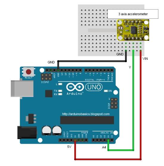
Accelerometer connection (Y-axis)
The accelerometer makes the LEDs much more fun and interactive. We will only be using the Y-axis of the accelerometer in this sketch. By tilting the accelerometer from one side to the other, the LEDs react and respond accordingly. The accelerometer is an essential component of the digital spirit level sequence. That's right ! You can use this sketch to create your own spirit level. This digital version can also be used to measure angles !
Have a look below to see how to hook up the accelerometer to the Arduino. The Y-axis is connected to the Arduino analog pin 4. If you wanted to use the X and Z axis, connect them to one of the other available analog pins (eg. A3 and A5).
Let the fun begin !!
Now that you have the Arduino code uploaded to the Arduino, and have made all of the necessary wire/component connections, it is time to turn on the power supply.
Sequence 1: Cylon with Hue control
The LEDs will move from one end of the strip to the other. It should start off as a RED cylon effect. As you turn the potentiometer clockwise, the colour of the LEDs will change and move through the various colours of the rainbow. If the potentiometer reading gets back to zero (fully anti-clockwise), it will move to sequence 2.
Sequence 2: Cylon with brightness control
You will see that the LEDs have turned off. The potentiometer readings correlate with the LED brightness. At the start of this sequence, the potentiometer readings will be zero, therefore the brightness will be zero (LEDs turned off). As you turn the potentiometer clockwise, the readings increase, and so will the brightness of the LEDs.
Sequence 3: Comet effect with Hue and direction control
This is where the real fun begins. You control the hue of the leading LED with the potentiometer, however the LED will move along the LED strip as though it were affected by gravity. As it hits the end of the LED strip, it will bounce for a while and eventually come to a stop. The more you tilt the accelerometer, the greater the acceleration of the leading LED. The trailing LEDs have an interesting randomised glow, which creates the "comet" effect.
Sequence 4: FireStarter / Rainbow effect : Hue and direction control
The initial colours of LEDs in this sequence creates a fire-like animation. As the leading LED moves along the LED strip, it appears to ignite the LEDs in its path, leaving a fire trail behind it. The fire effect is best when you turn the potentiometer clockwise slightly to introduce a small amount of yellow into the mix of colours. As you turn the potentiometer further clockwise, the fire trail turns into a pretty rainbow trail. The accelerometer affects the leading LED in the same way as the previous sequence.
Sequence 5: Digital spirit level
This sequence was my original idea for this project, however I thought it would be nice to share some of the other cool effects I created on my journey of discovery. The idea was to make a digital version of a spirit level. I originally wanted the LEDs to represent a spirit level bubble that would "float" according to the vertical/horizontal position of the LED strip. However, as I played around with this sketch, I discovered that it could potentially be used to measure the angle of the strip relative to the horizon. The angle can be determined by the illuminated LED. If the strip is horizontal, the illuminated LEDs will be close to the middle of the strip, and their colour will be green. If the strip is vertical, the illuminated LEDs will be close to end of the strip, and their colour will be red. The colour is just an additional visual indicator.
Concluding Comments
The NeoPixel Digital RGB LED strip is a lot of fun. The FastLED library makes for easy programming, and allows you to get up and running really quickly. 144 LEDs on a single strip means you have plenty of room for creative algorithms and lighting effects. Add a few sensors, and "pretty" quickly turns into "awesome" !!