In this tutorial, I will show you how to configure and extract data from the magnetometer (HMC5883L) sensor on the GY-80 10DOF module from ICStation. While there are some very good libraries on the internet which will give you full access to this sensor, I will show you what you need to know without using a library. This means that it may get a bit technical at times, but I will hold your hand along the way and provide explanations as required. I would also recommend that you watch the complete video from start to finish - as the video provides really useful information.
This tutorial does not use any external libraries. It does use the Wire library for I2C communication. However, there is no extra download required to access the Wire library. If you are looking for a library specific for the HMC5883L sensor, then I would recommend one of these:
Like I said - you do not need an HMC5883L library for this tutorial. The libraries above are listed for those who wish to learn more about this particular sensor.
I generally use the ZIP file for Windows and never seem to have any issues. There are downloads available for all the major operating systems.
ARDUINO CODE:
I have created a Gist for the Arduino code to configure and extract data from the HMC5883L sensor. However, I also have a GitHub repository which aims to capture the code for all of the sensors on the GY-80 module. Code for the other sensors will become available in due time. Meanwhile, have a look at the code below for the HMC5883L sensor:
This code will set all axis values to 1000 upon startup. Moving the GY-80 module around will result in a value greater or less than 1000, however, returning the sensor back to it's original position, should result in values very close to 1000 on each axis. I chose to introduce this calibration in order to avoid negative values, and I liked the fact that I could set a heading with values that were easy to remember.
The magSetting function was created to easily configure the magnetometer. Make sure to look at the video and also the datasheet for further information about calibrating the magnetometer.
The getReadings function was created to easily retrieve the magnetometer axis data. I chose to use Single measurement mode in this tutorial.
Hooking it up:
You can communicate with any of the sensors on the GY-80 module using I2C. The HMC5883L magnetometer sensor is no different. You will need four connections between the Arduino UNO and the GY-80 module. Have a look at the diagram below for the connection diagram and table.
Fritzing diagram
Project pictures
Concluding comments
The HMC5883L sensor on the GY-80 module is quite interesting and works relatively well. There are a number of other sensors on the GY-80 module which can provide complementary positional data. At some point, I plan to come back and explain some of the other sensors on this module, but first I would like to create a real-life project using the magnetometer. So stay tuned. You may want to subscribe to my social networks or to this blog to be notified of that project when I complete it.
I would like to thank ICStation for their collaborative efforts. Their contribution was invaluable to this tutorial's existence.
If you like this page, please do me a favour and show your appreciation :
A tiny board which can turn your computer into an - Oscilloscope - Waveform generator - Logic analyser - Multimeter - and Power supply.
Great for makers or hobbyists with limited bench space or limited funds. Perfect for students and anyone starting out in the field of electronics
As you will see in the video below, I take a prototype of the EspoTek Labrador for a spin, and try out all of the functions that this board can provide.
I use an Arduino UNO, a couple of 433MHz RF modules, some LEDs and a speaker to see just how useful this board will be for my hobby requirements.
I have been wanting an Oscilloscope for quite some time, and while this board does not necessarily win against a benchtop oscilloscope on a side-by-side comparison of specifications, it does make up for it somewhat in terms of price, space (or footprint), usability, and wide range of functionality. But does it actually function as an oscilliscope? Is it useful ? Will it do what I need it to do? Or will I still need to buy that expensive oscilloscope that I have been saving up for?
Have a look at my review below, and tell me what you think.
This is a guest post by the EasyEDA team. I would like to thank EasyEDA for providing this tutorial for everyone to enjoy. All information within this post was provided by EasyEDA.
Description
None of us could deny the fact that we would love with to play with LED’s and lighting stuff. I love to play with LED’s and create attractive lighting effects. This project was a result of such an attempt where I created a stunning RGB light effect using the popular development platform Arduino Nano. Let’s see the circuit, code and instruction on building this project:
No libraries are required for this project. The Arduino IDE can be downloaded from the Arduino website. Here is the download link.
ARDUINO CODE:
Preparing the LED strips
Cut down the LED strips into 10 single pieces. Make sure you cut them into equal halves and make sure that only the copper conduction plate in the strip is cut. Making a wrong cut disrupts the electrical conductivity between the LED’s. After cutting down into separate strips, you will need to connect each strip using a Dupont wire connectors.
I have made a custom control board that incorporates an Arduino Nano. The control board is used to boost the incoming signal from Arduino and lights up the corresponding LED strips.
I used a free Online circuit and PCB designing platform called EasyEDA to develop my control board. It is pretty easy to use especially because of the large library of parts to choose from. Once the design is complete, you have the option to order it through EasyEDA. They offers great prices on custom PCB manufacturing. I have added 10 connection points for 10 LED strips. Each RGB LED strip is controlled by one of the Arduino Nano digital pins.. Transistors Q1,Q2,Q3….Q10 act as a switch for these LED strips for controlling 12V strips via a 5V signal from the Arduino. And switches S1,S2..S4 were added to be able to select the effect on the strip. The schematic can be seen below:
Schematic
You can access the actual EasyEDA schematic by clicking on the image below:
After completing the PCB design, you can click on the Fabrication icon.
You will then have access to the PCB order page which will allow you to download your PCB Gerber files that can be sent to any manufacturer. However it is a lot easier (and cheaper) to order it directly from EasyEDA. Here you can select:
the number of PCBs you want to order
the number of copper layers you need
the PCB thickness
copper weight
and even the PCB color
After you’ve selected all of the options, click “Save to Cart” and complete you order. You will then get your PCBs shipped a few days later.
Connect the LED strips through the connection points in the board. Make sure that you connect these correctly (push the connectors all the way onto the pin), because the chances of a short increase significantly with the number of wires connected. Once all the connections are done all that left is to install your Arduino Nano (pre-programmed with the Arduino code above), and to power the PCB with a 12V power supply.
This is an Arduino based home security project that uses the power of "Cayenne" for extraordinary capabilities.
Cayenne Beta
Cayenne is a new IoT drag and drop platform originally released for the Raspberry Pi, but now available for Arduino. Cayenne makes the task of connecting your Arduino to the internet as simple as possible. All of the complexity of internet connectivity is hidden within the Cayenne library.
You can easily create a Network of Arduinos and build an IoT system which can be managed and operated within the Cayenne dashboard. This dashboard is accessible through your browser or via the Cayenne smart phone app (on IOS or Android).
The feature I liked the most, was the ability to change the position of sensors or actuators on the Arduino without having to re-upload Arduino code. I could manage the changed position from within the Cayenne platform. The other feature that I liked was the ability to setup actions based on custom triggers. You can use Cayenne to trigger a whole range of functions, for example: play a sound, move a motor, light up an LED, or to send alert notifications via email or SMS.
Cayenne is in Beta at the moment, so there are a few minor bugs here and there, but overall - I give it a thumbs up - it is definitely worth checking out.
In order to fully experience this new IoT platform, I decided to create a project to really put it through its paces. This is what my Security Project will need:
It will use two Arduinos, one connected to the internet via an Ethernet shield, and the other via WIFI.
Two detectors - a PIR sensor and a laser trip wire.
If the sensors are tripped, the person has 10 seconds to present an RFID tag to the Grove RFID reader:
If a valid RFID tag is SUCCESSFULLY presented within the time limit, a nice personalised greeting will be played to that person using a Grove - Serial MP3 player
If a valid RFID FAILS to be presented within the time limit, an Alarm will sound, and I will be notified of the intrusion via an SMS alert.
The Cayenne dashboard will show the status of the sensors, and I will have full control over my security system via the web interface (or smartphone app).
The sensors will be attached to a different Arduino to that of the Grove MP3 player and the RFID tag reader, which means that there will have to be some level of communication between the two Arduinos. In fact, the cross communication will be vital to the success of this project.
The following flow diagram shows the Security project process. It is a high level view of the decisions being made by each Arduino in response to various events.
Triggers Flow Diagram
The following flow diagram aims to highlight the various triggers set up within Cayenne to get this Security system to work.
Arduino IDE and Library Downloads
You will need an Arduino IDE to upload code to the Arduino and the Seeeduino Cloud. Here is the link to the Arduino IDE: Arduino IDE - download location
The Cayenne service requires that you download and install the Cayenne Library into your Arduino IDE. You can get the Cayenne Library from here: Cayenne Library File - Download
Cayenne Connectivity Setup
The Seeeduino Cloud needs to be prepared for use with Cayenne. Normal operating/setup instructions can be found here: Seeeduino Cloud WIKI page
Once you have successfully connected Seeeduino Cloud to your WIFI network, you can add it to the Cayenne Dashboard by making the following selections from within the Cayenne Web application:
Add New
Device/Widget
Microcontrollers
Arduino
Ensure Seeeduino Cloud is connected to WIFI network - the select the NEXT button
Select - Arduino Yun: Built-in Ethernet - ticked
Providing you have already installed the Cayenne library as described above - you should be able to copy and paste the code to the Arduino IDE and upload to the Seeeduino Cloud.
If successful, you should see the Arduino Yun board appear within the Cayenne Dashboard. If not, then seek help within the Cayenne forum.
The Arduino UNO with WIZNET 5100 - Ethernet Shield also needs to be prepared with Cayenne
Add New
Device/Widget
Microcontrollers
Arduino
Ensure Arduino is powered, and Ethernet shield is connected to your internet router via an Ethernet cable
Copy and paste the code to the Arduino IDE and upload to the Arduino UNO.
If successful, you should see the Arduino Uno board appear within the Cayenne Dashboard. If not, then seek help within the Cayenne forum.
If you have the Ethernet shield with the WIZNET 5200 chip, then you may need to download a specific Ethernet library in addition to the Cayenne library.
Just follow the instructions within the Automatically generated sketch provided - when you select your specific Arduino/Ethernet/WIFI shield combination. If you need further instructions on connecting your device to Cayenne - then please visit the myDevices website for the online documentation.
ARDUINO CODE (1)
Code for Arduino UNO with Ethernet Shield:
The following code will need to be uploaded to the Arduino UNO:
ARDUINO CODE (2)
Code for Seeeduino Cloud:
The following code will need to be uploaded to the Seeeduino Cloud:
Fritzing diagram (1)
Fritzing diagram for Arduino UNO with Ethernet
Please click on the picture below for an enlarged version of this fritzing diagram
Fritzing diagram (2)
Fritzing diagram for Seeeduino Cloud
Please click on the picture below for an enlarged version of this fritzing diagram
Cayenne Dashboard Setup - GUI
The Arduino code only provides half of the functionality of this project. The Cayenne Dashboard needs to be setup to provide the rest of the functionality. The following instructions will show you how to add each of the widgets required for this Home Security project.
Arduino Ethernet - Master Switch
The master switch allows me to turn the security system on and off. When I turn the MASTER SWITCH ON, the laser beam will turn on, and the sensors will start monitoring the area for intruders. This widget is NOT associated with a physical switch/sensor on the Arduino - it uses virtual channel 0. We need to add the Master switch to the dashboard:
Add New
Device/Widget
Actuators
Generic
Digital Output - Control a Digital Output
Widget Name: Master On Off Switch
Select Device: Arduino Ethernet
Connectivity: Virtual
Pin: V0
Choose Widget: Button
Choose Icon: Valve
Step2: Add Actuator
We will add a trigger later to get this button to automatically turn the Laser beam on.
Arduino Ethernet - PIR Sensor
This sensor will be used to detect movement in the room. If a person walks into the room, this sensor will detect movement, and will trigger a message to be played on the Grove Serial MP3 player. The message will aim to get the person to identify themselves. They identify themselves by placing their RFID tag in close proximity to the Grove RFID reader. If the tag is valid, a "Welcome home" message is played on the Grove MP3 player. If a valid tag is not presented to the reader within 10 seconds, an Alarm will go off ("Alarm sound" played on Grove MP3 player.)
The PIR sensor is connected to digital Pin 6 of the Arduino, however, it is mapped to virtual pin 1 for better synchronisation with the Cayenne dashboard. This was done to capture ALL detections - as the PIR sensor could change from a LOW to HIGH and back to LOW state in between a Cayenne state check - and therefore, Cayenne could miss this motion detection.. Therefore we need to assign the PIR sensor to a virtual channel in the following way:
Add New
Device/Widget
Sensors
Motion
Digital Motion Sensor - Motion Detector
Widget Name: PIR sensor
Select Device: Arduino Ethernet
Connectivity: Virtual
Pin: V1
Choose Widget: 2-State Display
Choose Icon: Light
Step2: Add Sensor
Select Settings from the PhotoResistor
Choose Display: Value
Save
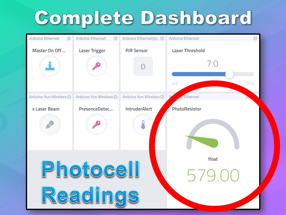
Arduino Ethernet - Photoresistor
This sensor will be used with the laser beam to create a laser tripwire. If the sensor detects a change in light levels (drops below the threshold), it will activate the laser trigger button on the dashboard. The person will then be required to identify themselves etc etc (similar to the motion detection by the PIR sensor). The photoresistor widget will display the raw analog reading from the sensor (connected to A2), but is associated with virtual channel 2. I used a virtual channel for more control over this sensor. To add the Photoresistor to the dashboard:
Add New
Device/Widget
Sensors
Luminosity
Photoresistor - Luminosity sensor
Widget Name: PhotoResistor
Select Device: Arduino Ethernet
Connectivity: Virtual
Pin: V2
Choose Widget: Value
Choose Icon: Light
Step2: Add Sensor
Arduino Ethernet - Laser Trigger
The laser trigger is just an indicator that someone tripped the laser beam. The state of this widget is used to notify the Seeeduino that a presence has been detected. This widget is associated with virtual pin 4 on the Arduino UNO with Ethernet.
Add New
Device/Widget
Actuators
Generic
Digital Output - Control a Digital Output
Widget Name: Laser Trigger
Select Device: Arduino Ethernet
Connectivity: Virtual
Pin: V4
Choose Widget: Button
Choose Icon: Lock
Step2: Add Actuator
Arduino Ethernet - Laser Threshold
The laser threshold is used to manually configure the light level at which the laser trigger will trip. When the photoresistor value drops below the threshold value, the laser trigger icon will activate. This allows the threshold value to be updated from the Cayenne dashboard, rather than having to manually adjust the value in the Arduino code. Also, this threshold can be set remotely, in that you don't have to be near the Arduino to change this value. A very useful feature of this Security system. This widget is associated with virtual pin 5 on the Arduino UNO with Ethernet.
Add New
Device/Widget
Actuators
Generic
PWM Output - Control a PWM Output
Widget Name: Laser Threshold
Select Device: Arduino Ethernet
Connectivity: Virtual
Pin: V5
Choose Widget: Slider
Slider Min Value: 0
Slider Max Value: 10
Step2: Add Actuator
The max value of the slider is 10 - due to a current bug in the Cayenne software. Once resolved, this value (as well as the relevant Arduino code) will need to be updated.
Seeeduino Cloud - Presence Detected
The presence detected widget is there to notify the Seeeduino Cloud that a presence has been detected on the Arduino Uno with Ethernet shield. When the PIR sensor detects movement or if the laser tripwire is tripped, Cayenne will change the state of the Presence Detected widget from LOW to HIGH. This is used within the Seeeduino Cloud to trigger the message "Place your keys on the Mat" . If a valid RFID tag is read by the Grove RFID reader, then this widget's state will change back from HIGH to LOW, and the MasterSwitch will be deactivated - turning the Security system off. This widget is associated with Virtual pin 6 on the Seeeduino Cloud.
Add New
Device/Widget
Actuators
Generic
Digital Output - Control a Digital Output
Widget Name: Presence Detected
Select Device: Seeeduino Cloud
Connectivity: Virtual
Pin: V6
Choose Widget: Button
Choose Icon: Lock
Step2: Add Actuator
Seeeduino Cloud - Intruder Alert
If a valid RFID tag is not read by the Grove RFID reader within 10 seconds of a presence detection event, an alarm will sound, and this widget will be activated. This will trigger a notification event - to notify me of the unauthorised intrusion - via SMS or email. I will also have a visual indicator on the Cayenne dashboard that an intrusion has taken place. This widget is associated with Virtual pin 7 on the Seeeduino Cloud.
Add New
Device/Widget
Actuators
Generic
Digital Output - Control a Digital Output
Widget Name: Laser Trigger
Select Device: Seeeduino Cloud
Connectivity: Virtual
Pin: V7
Choose Widget: Button
Choose Icon: Thermometer
Step2: Add Actuator
Seeeduino Cloud - Laser Beam
The laser beam widget was created to allow for full control over the laser beam. The laser beam can be turned on or off from the Cayenne dashboard, and a connected to digital pin 7 on the Seeeduino Cloud.
Add New
Device/Widget
Actuators
Light
Light Switch - Turn On/Off a Light
Widget Name: xLaser Beam
Select Device: Seeeduino Cloud
Connectivity: Digital
Pin: D7
Choose Widget: Button
Choose Icon: Light
Step2: Add Actuator
Cayenne Triggers
Now that all of the widgets have been added to the Dashboard, there is just one more step to complete the Security System. We need to setup the triggers. These triggers provide a level of automation that is easy to create within Cayenne, but would be very complicated otherwise. I set my triggers up as per the table below. Each row represents one of the triggers within my Cayenne dashboard. If you would like to see an example of how to add a trigger - please have a look at the video at the top of this tutorial.
Concluding comments
I used many different elements to put this home/office security project together - Multiple Arduinos were connected to the internet, both controlled by a web/smart phone app, cross-communication/synchronisation between the Arduinos, and the use of multiple sensors and modules including a laser beam !
This was way more than just a simple PIR sense and alarm project. I now have a personalised greeting and reminder system when I walk in the door. Everyone else has their own personalised greeting. I can enable my Security System remotely, from two blocks away, and if I wanted to - I could enable it from the other side of the world. I know instantly when someone has entered my house/office.... with an SMS alert straight to my phone.
This project could easily be extended:
Press a button on my phone to manually trigger/play a specific message/sound/song
Take a picture of the intruder
Introduce fire or leak detection aswell
Add other environmental sensors - Temperature / Humidity
Connect it to lamp/light - creating a security light
I am sure you can think of more things I could do with this system. In fact, why don't you mention your ideas in the comments below.
Cayenne was instrumental in getting this project to work. I don't think I would know where to start if I had to do this project without this cool IoT platform. I think I will definitely be trying out a few more projects using Cayenne, and should you want to do the same, then please make sure to join Cayenne Beta:
Here is the link you need to get to the right place: Cayenne Beta Link
If you like this page, please do me a favour and show your appreciation :
This is a fun project that will surely impress anyone you make this for. If you are having a "Disco" themed party, you cannot have a boring old cake. Let me tell you, this is probably the only Arduino project that my wife has ever been willing to be a part of. She did the hard work of putting the cake together, and I, well.... I was in charge of lighting. My biggest fear was that one of the wires would come loose and ruin the event at the most critical moment... While a wire did come loose, I managed to fix it in time before the guests arrived. Ok enough of my monologue, let me show you how to make one of these things.
Note: powering this project using batteries is possible, but not recommended, and done at your own risk.
You will also need a Disco Ball Cake which you will have to make(or buy).My wife made this one. And as you will see shortly, the cake on the inside was Pink, because it was a strawberry cake.
Arduino Libraries and IDE
You can get the Arduino IDE from here: https://www.arduino.cc/en/Main/Software I used version 1.6.4, which is probably way out of date... but works fine nonetheless.
You can get information about how to use the FastLED library here: http://fastled.io/ And you can download it from here: FastLED Library I used version 3.0.3, which is also probably out of date.
ARDUINO CODE:
ARDUINO CODE DESCRIPTION:
FastLED Library: You need to make sure that you have downloaded and installed the FastLED library into your Arduino IDE. The library is included in this sketch otherwise the FastLED functions will not work.
The "NUM_LEDS" variable: tells the Arduino how many LEDS are in use. In this case, we have 4 LED rings, with each LED ring containing 16 LEDs, and therefore a total of 64 LEDs. If you define a lower number, for example 16, then the sketch would only illuminate the LEDs on the first LED ring.
The "DATA_PIN" variable: tells the Arduino which Digital Pin to use for data transmission to the LED ring. In this case, I am using Digital Pin 9.
Other variables: I have a couple of other variables which are used for LED randomisation and hue control. Hue is the colour of the LED. By incrementing the hue variable, you can get the LEDs to cycle in a rainbow-like pattern. The "hue" variable is a "byte", which means that it will only go up to a maximum value of 255, before it jumps back down to zero.
Initialisation Code: If you have a different LED ring to the one in this tutorial, you may have to modify the initialisation code. This LED ring has a WS2812-B chipset (according to the ICStation website), and so this line:
FastLED.addLeds(leds, NUM_LEDS); Will tell the FastLED library which chipset is being used (NEOPIXEL), the pin used for data transmission (DATA_PIN), the LED array to be controlled (leds), and the number of LEDs to be controlled (NUM_LEDS).
In the "loop()": section of the code: the "hue" variable is incremented to create a rainbow effect, and a random LED is selected using the FastLED's random8() function.
The random8(x) function: will randomly choose a number from 0 to x.
The randomSeed() function: is there to help "truely randomise" the number. This is helped by reading the randomness of a floating analogPin (A0). It doesn't have to be analogPin 0, it can be any unused analog pin.
leds[rnd].setHSV(hue,255,255): This line sets the random LED to have a hue equal to the "hue" variable, saturation equal to 255, and brightness equal to 255. Saturation equal to zero will make the LED shine white. Brightness of zero essentially turns the LED OFF.
FastLED.show(): No physical changes will be made to the LED ring display until a message is sent from the Arduino to the Digital input pin of the LED ring. This message is transmitted when you call the FastLED.show(); function. This tells the LED rings to update their display with the information contained within the led array (leds). So if you set all LEDs to turn on, the board will not illuminate the LEDs until the FastLED.show(); function is called. This is important to know - especially when trying to design your own LED sequences.
The delay(50) line: will set the amount of time between flashes to 50 milliseconds. You can change the delay to increase or decrease the number of flashes per second.
The leds[i].fadeToBlackBy( 180 ) function: essentially fades the LEDS by 180 units. You can increase or decrease this number to achieve the desired fade speed. Be warned however, that if you forget to call this function or if you fail to fade the LEDs sufficiently, then you may end up with ALL LEDs turning on, which could potentially destroy your Arduino board - i.e. depending on the number of LED rings you have, and how you have chosen to power them.
The Cake
Slide 1 - Base Plate: It is important to create the base plate with all of the electronics fitted and in working order BEFORE you put the Cake onto it. Trying to fit wires/cables LEDs and circuits under the base plate while there is a Cake ontop is a recipe for disaster. So prepare the base plate first, and then move to the cake making part later.
Slide 2 - Bake Cake: You will need a couple of hemisphere cake pans to make the two sides of the ball. You have to make a relatively dense cake to withstand the overall weight of the cake, icing and fondant, and to maintain it's shape. Once cooled and chilled, you can place them ontop of each other to form a sphere. They are held together by a layer of icing between them.
Slide 3 - Fondant Icing: The fondant icing has to be rolled out on a special non-stick mat. We found that adding a bit of flour helped to reduce the stickiness. There are special rollers which ensure that the thickness of the fondant is consistent throughout. You then have to cut them into square pieces (about 1 cm squares worked well for us). The squares are then painted Silver with a special/edible silver fondant glaze. You may need to use a few coats, and allowing it to dry between coats.
Slide 4 - Iced Cake on Base: The cake can either be iced on or off the base plate... probably better to do it off the base plate. But if you decide to do it on the base plate, you will need to protect the LEDs from stray icing that may fall from the cake (in the process). Once the cake has been fully iced (with icing/frosting), you will need to place the cake into the central position on the board. There may be a chance that the cake may slide from the base... so do what you need to do to make it stay put.
Slides 5-7 - Place Fondant Squares: While the icing is still soft, you will then need to quickly, methodically and tirelessly place the fondant squares in a horizontal linear pattern around the cake. Work your way towards the north and south poles of the cake doing one row at a time. You can cut a fondant circle for the north pole of the cake. In slide 7, you will see a hole at the top of the cake. This was made to cold a plastic canister inside, which would be used later the hold the decorations in place at the top of the cake. Do this before placing the fondant circle at the top of the cake.
Slide 8 - Add Glitter: After placing all of the fondant squares onto the cake, it is very possible that some of the Silver glaze may have been wiped off some of the squares. This is where you go over it again with a few more coats of silver glaze, and on the last coat, before it dries, you can sprinkle some edible glitter all around the cake to give it that extra shine.
Slide 9 - The end product: The final step is to add some wire sparklers and some other decorations to the top of the cake. Push the wires through the fondant cap at the north pole into the canister within. This will hold the wires in place without ruining all of your hard work.
LED Ring pins
WS2812-B chipset: This LED ring uses the WS2812-B chipset, and has 4 break-out pins (GND, 5V, Din, Dout)
Power: To power this module, you need to provide 5V and up to 1A of current
Signals: To control the LED ring, you need to send signals to it via the Digital Input pin (Din). You can connect another LED ring to this one by utilising the Digital Output pin (Dout)
Power Usage Guide
General Rule: Each individual LED on the ring can transmit Red, Green and Blue light.The combinations of these colours can make up any other colour. White light is made up of all three of these colours at the same time. Each individual colour will draw approximately 20mA of current when showing that colour at maximum brightness. When shining white at maximum brightness, the single LED will draw approximately 60mA.
Power multiplier: If each LED can draw up to 60mA and there are 16 LEDs on a single LED ring, then 16x60mA = 960mA per LED ring. To be safe, and to make the maths easier, you need to make sure that you provide enough current to accommodate 1A per LED ring. So 4 LED rings will need a 5V 4A power supply if you want to get full functionality out of the modules.
Fritzing diagram
Connecting ONE LED Ring to the Arduino- (Click to enlarge)
3 wires: You only need 3 wires to connect to the LED ring. If you only plan to light up a couple of LEDs at any one time this should be ok.
The SAFE WAY: A safer way to do this is to use an external power supply to power both the Arduino and the LED ring.
Electrolytic capacitor: By connecting a large 4700 uF 16V Electrolytic capacitor between the positive and negative terminals of power supply leads, with the negative leg of the capacitor attached to the negative terminal of the power supply, you will protect your LED rings from any initial onrush of current.
Protecting Resistor: It is also advisable to place a 300-400 ohm resistor between the Arduino's Digital Pin 9 (D9) and the LED Ring's Digital Input pin (Din). This protects the first LED from potential voltage spikes
Suitable wires: If you plan to chain a few of these LED rings together (see below), then you will probably want to keep the wires as short as possible and use a decent guage wire that can handle the current being drawn through them.
Connecting TWO LED Rings to the Arduino- (Click to enlarge)
Three extra wires:You only need 3 extra wires to connect an additional LED ring. A wire needs to connect the Digital output (Dout) of the first LED ring to the Digital Input (Din) of the 2nd LED ring.
Stay safe: Once again, a safer way to do this is to use an external power supply, a large electrolytic capacitor at the terminals, and a 300-400 ohm resistor between the Arduino and the first LED ring's digital input pin.
Connecting FOUR LED Ring to the Arduino- (Click to enlarge)
Sixty Four LEDs:You need 3 extra wires for each additional LED ring. 4 LED rings provides a total of 64 LEDs.
Watch the AMPS:At full brightness, this setup could potentially draw up to 4amps (or roughly 1 amp per LED ring)
External Supply essential: It is essential to use an external power supply to power these LEDs when there are so many of them. If you don't use an external power supply and you accidentally illuminate ALL of the LEDs, then you are likely to damage the microcontroller from excessive current draw.
Connection Tables
How to connect ONE LED Ring to the Arduino- (Click to enlarge)
How to connect TWO LED Rings to the Arduino- (Click to enlarge)
Concluding comments
In this tutorial I showed you how to go about decorating a Disco Ball cake and also showed you how to use the RGB LED rings from ICStation. If you look at the video you will see just how versatile these LED rings are. I would like to thank my wife for providing such an exciting project to work on, and ICStation for their collaborative efforts. Please make sure to share this project with all of your friends and family.
If you like this page, please do me a favour and show your appreciation :