.
Bluetooth Android Processing 1 Reviewed by Unknown on 23:54 Rating: 4.5

Bluetooth Android Processing 1


PART ONE


Introduction

This is a four part tutorial which will take you through step-by-step on how to create Android apps on your Mobile device that will allow you to communicate with your Arduino over Bluetooth. This tutorial is based upon the Windows environment and an Android device like the Samsung Galaxy S2 Phone.
I will take you through setting up your computer and phone, and will move through in stages so that you understand what each part of the bluetooth code is actually doing. Obviously you will need to ensure that you have a Bluetooth Shield on your Arduino to be able to walk through this tutorial with me.
If you are not interested in the step-by-step instructions, you can jump straight to the end (Part 4) which will have the complete Arduino and Android/Processing code that was used in the following video:

The Goal of this project (Video)


Setting up Processing for Android applications:
For the latest and most up to date version, please follow the instructions on this website: http://wiki.processing.org/w/Android

    Step One:
    Download the Android SDK from this website:
    http://developer.android.com/sdk/index.html
    Android SDK download link
    Android SDK Download:
    Make sure to select the "Use and Existing IDE" link, as per the picture below.
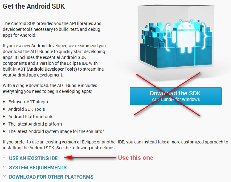


    When you select the "Use an Existing IDE" link, it will then show you the appropriate download to use. This is what it should look like.

    Select the "Download the SDK Tools for Windows" link.
    Once you have downloaded the Android SDK, go ahead and install it as per the instructions below.
    These instruction can also be found here.
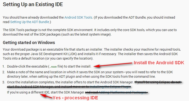


    Installing the necessary packages in the Android SDK Manager program
    Make the following 3 selections:
    • Tools: Android SDK Platform-tools
    • API 10: SDK Platform
    • Extras: Google USB Driver
    Then select the button on the bottom-right to install your selections.

    Here is a picture of the Android SDK Manager selections:
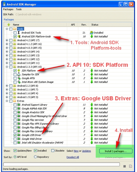

    While you may decide to download other packages,
    you MUST download API 10: SDK Platform .
    Do not leave this one out !!


    Processing.org Download Link
    Step Two: Processing Download

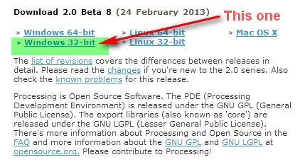
    Download the latest Processing IDE(version 2.0 Beta 8) from this website:
    http://processing.org/download/

    I am using Windows 7, and have chosen to download the Windows 32 bit version as shown below.


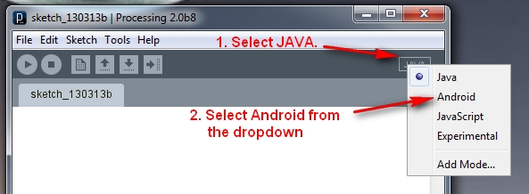
    Load Processing, and switch to Android mode, as per the image below.


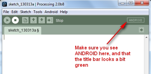
    You should now have an empty sketch window which looks something like this.


    Step Three: Setting up the Android Hardware device (Phone)
    For the latest steps you can have a look at this site:
    http://developer.android.com/tools/device.html

    However, these are the ones that I carried out:

    Turn on USB debugging on your Android Phone:
    To find out what Android Version you are on, have a look at
        Settings > About Phone : look for heading "Android Version".
    • My Android version is 2.3.4 on my Samsung Galaxy S2.
    To Enable USB Debugging:
       
    Settings > Applications > Development > Select (or Enable) USB debugging

      For those of you who have a different Android version, have a look below:


      Downloading the USB driver for your Android Phone(Windows Users)
      If you are developing on Windows and would like to connect an Android-powered device to test your applications, then you need to install the appropriate USB driver. Have a look at this site for more information on how to download the USB driver for your phone:
      http://developer.android.com/tools/extras/oem-usb.html

      I have a Samsung Galaxy S2 phone, so I had to go to the Samsung Site here:
      http://www.samsung.com/us/support/downloads

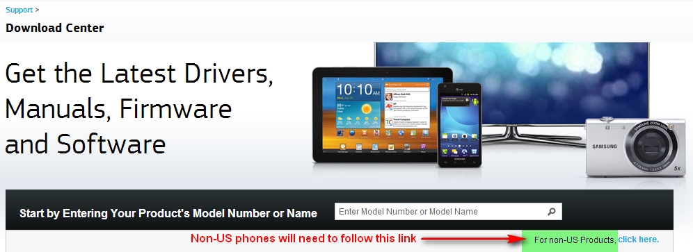
      But because I am not in the USA, I had to click on the link for "non-US products":
      http://www.samsung.com/us/support/downloads/global

      You will need the model number of your phone:
      On the Samsung Galaxy S2, you can go into
          Settings > About Phone => Model number. Otherwise, it is located behind the battery.
      • My Phone's Model Number is: GT-I9100
      See the image below for the link to press if you have a non-US phone.


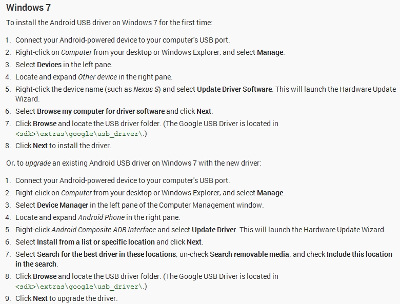
      Then I continued with the install of the USB driver as per the document below:
      http://developer.android.com/tools/extras/oem-usb.html


      Step Four: Android-Processing Sketch
      We will now test our our current setup and make sure that we can run a simple Processing Sketch on the Phone. Bluetooth functionality will be tested later on, so all we need for this step, is our computer, our Android phone, and a USB cable. While it is possible to run this sketch without an Android phone (by using the emulator), I personally do not have the patience to wait an eternity while the emulator boots up... (yes, it takes an eternity)... In this tutorial, we are going to test it on the device (phone).
      This sketch has an orange background and a black circle which you can move around the screen with your finger (that's it) - I did say it was going to be a simple sketch.

      Copy and paste the following Android-Processing sketch into the IDE, and then press the (Run on Device) button, which is the triangle button or press Ctrl-R.


      Android/Processing Sketch 1: Circle Dragger

      1
      2
      3
      4
      5
      6
      7
      8
      9
      10
      11
      12
      13
      14
      15
      /*Circle Dragger: Simple Android-Processing Sketch written by ScottC on 13/03/2013.
      Visit: http://arduinobasics.blogspot.com/
      */

      int circleWidth = 150;
      void setup(){
      orientation(LANDSCAPE);
      }
      void draw(){
      background(255,100,0);
      fill(0);
      ellipse(mouseX,mouseY,circleWidth,circleWidth);
      }


      You should see an orange screen appear on your phone. Move your finger across the screen and watch as the black circle follows your finger.
      No, not rocket science, but hopefully everything worked as planned. If you want to change the colour of the background or circle, this is a good site:
      http://www.colorpicker.com/


      Step Five: Bluetooth testing:
      We are now going to walk through Bluetooth connectivity. While we could just use a library to do all the heavy lifting for us, I decided to explore Bluetooth functionality from scratch. This will hopefully provide greater returns in the long run. Ok, lets create a new Android/Processing Sketch which changes its behaviour depending on whether Bluetooth is enabled or disabled when the sketch is run. We will display a red screen when Bluetooth is switched off, and green when Bluetooth is switched on.

      To enable Bluetooth on my Samsung Galaxy SII phone:
      • Settings >Wireless and Network > Bluetooth Settings > Bluetooth (Turn on Bluetooth) - check the box

      To disable Bluetooth on my Samsung Galaxy SII phone:
      • Settings >Wireless and Network > Bluetooth Settings > Bluetooth - Uncheck the box

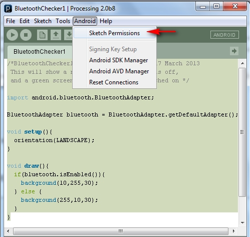
      In the processing/android IDE, you need to make sure that you update the AndroidManifest.xml file to grant specific permissions. You can either edit the file manually in the sketch folder, however, it is much easier and safer to do the following. In the processing/android IDE, select:
      •   Android > Sketch permissions  (as per the picture below)
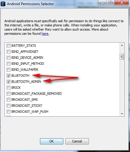
      • Make sure that BLUETOOTH and BLUETOOTH_ADMIN are selected (as per the picture below). Then press the OK button.

      Then copy and paste the following sketch into the processing/android IDE:


      Android/Processing Sketch 2: BluetoothChecker1
      1
      2
      3
      4
      5
      6
      7
      8
      9
      10
      11
      12
      13
      14
      15
      16
      17
      18
      19
      /*BluetoothChecker1: Written by ScottC on 17 March 2013
      This will show a red screen if Bluetooth is off,
      and a green screen when Bluetooth is switched on */


      import android.bluetooth.BluetoothAdapter;

      BluetoothAdapter bluetooth = BluetoothAdapter.getDefaultAdapter();
      void setup(){
      orientation(LANDSCAPE);
      }
      void draw(){
      if(bluetooth.isEnabled()){
      background(10,255,30);
      }
      else {
      background(255,10,30);
      }
      }


      When you run the BluetoothChecker1 sketch on the device, you will either see a red screen or a green screen depending on whether you had Bluetooth enabled or disabled at the time. Ok, pretty boring, but it is a start. What if we wanted to ask the USER if they would like to enable Bluetooth at the beginning? We could then change the appearance of the screen depending on their selected answer. Before we add this functionality, I would recommend that you read about the following concepts introduced in the next sketch.
      While it is actually possible to turn bluetooth on without asking for permission, I thought I would retain my manners for the following sketch:

      Android/Processing Sketch 3: BluetoothChecker2
      1
      2
      3
      4
      5
      6
      7
      8
      9
      10
      11
      12
      13
      14
      15
      16
      17
      18
      19
      20
      21
      22
      23
      24
      25
      26
      27
      28
      29
      30
      31
      32
      33
      34
      35
      36
      37
      38
      39
      40
      41
      42
      43
      44
      45
      46
      47
      48
      49
      50
      51
      52
      53
      54
      55
      56
      57
      /*BluetoothChecker2: Written by ScottC on 17 March 2013

      If Bluetooth is already ON when you run this sketch,
      the background will display BLUE.

      If Bluetooth is OFF when you run this sketch but you
      agree to turn it on, the background will display GREEN.

      If Bluetooth is OFF when you run this sketch and then
      choose to keep it off, the background will display RED.

      =======================================================*/


      import android.bluetooth.BluetoothAdapter;
      import android.content.Intent;
      int BACKGND=0; //Set the background to BLUE
      //Get the default Bluetooth adapter
      BluetoothAdapter bluetooth = BluetoothAdapter.getDefaultAdapter();

      /*The startActivityForResult() launches an Activity which is
      used to request the user to turn Bluetooth on.
      The following onActivityResult() method is called when the
      Activity exits. */

      @Override
      protected void onActivityResult(int requestCode, int resultCode, Intent data){
      if(requestCode==0){
      if(resultCode == RESULT_OK){
      BACKGND=2;
      //Set the background to GREEN
      }
      else {
      BACKGND=1;
      //Set the background to RED
      }
      }
      }
      void setup(){
      orientation(LANDSCAPE);

      /*IF Bluetooth is NOT enabled,
      then ask user permission to enable it */

      if (!bluetooth.isEnabled()) {
      Intent requestBluetooth =
      new Intent(BluetoothAdapter.ACTION_REQUEST_ENABLE);
      startActivityForResult(requestBluetooth, 0);
      }
      }
      void draw(){
      if(BACKGND==0){
      background(10,10,255);
      //Set background to BLUE
      }
      else if(BACKGND==1) {
      background(255,10,10);
      //Set background to RED
      }
      else {
      background(10,255,10);
      //Set background to GREEN
      }
      }

      I tried my best to explain the code via the comments within. I hope it made sense.


      Useful Links:

      Android Processing Wiki: http://wiki.processing.org/w/Android

      Here is a good tutorial which helped me put Processing and Android together:
      http://www.creativeapplications.net/android/mobile-app-development-processing-android-tutorial/

      And most importantly:
      The Android Developers site : Bluetooth


      Click here for PART TWO

      Click here for PART THREE

      Click here for PART FOUR


      If you like this page, please do me a favour and show your appreciation :

       
      Visit my ArduinoBasics Google + page.
      Follow me on Twitter by looking for ScottC @ArduinoBasics.
      Have a look at my videos on my YouTube channel.


      However, if you do not have a google profile...
      Feel free to share this page with your friends in any way you see fit.


      Description: Bluetooth Android Processing 1 Rating: 3.5 Reviewer: Unknown ItemReviewed: Bluetooth Android Processing 1
      Arduino UNO: LED Sensor, Part One Reviewed by Unknown on 22:30 Rating: 4.5

      Arduino UNO: LED Sensor, Part One

      As seen in the previous blog postings, the LED (Light Emitting Diode) was used to DISPLAY the result of various sensors. It was also used to create a variety of Light patterns or sequences.

      The LED is commonly used as an OUTPUT device, however, I have since found out: there is another option.

      You can use the LED as an INPUT device !!


      I have only tried this with a Yellow LED and a Red LED, however, this should work with any colour. Some sites recommend using a clear/transparent/colourless LED for best effect, but it depends on what you are trying to achieve.

      The LED responds better to light of the same wavelength that it emits. So a yellow LED responds better to yellow light, and a red LED responds better to Red light.

      The following experiment attempts to prove this theory.
      A Red and Yellow LED alternate and fade in to maximum brightness using PWM (Analog Output). Meanwhile, a separate LED is used as an INPUT device to receive the light. The value obtained is plotted using a processing sketch.

      The chart above used a Yellow LED to measure the light emitted from a Red and then a Yellow LED.
      As the Yellow LED gets brighter, the INPUT LED takes less time to discharge, and thus produces a lower result. On the other hand, the Red LED has little effect on the INPUT LED, despite it's brightness.
      Ambient light will produce different graph patterns.

      Parts Required:
      • Arduino UNO
      • 2 x Yellow LEDs
      • 1 x Red LED
      • 3 x 330 ohm Resistors (choose resistors suitable for your LEDs)
      • 5 wires to connect the circuit
      • Breadboard
      • Processing software
      Here is the Sketch:

           Created with Fritzing : http://fritzing.org/


      Here is the Arduino Code: which was adapted from this site.
       1
      2
      3
      4
      5
      6
      7
      8
      9
      10
      11
      12
      13
      14
      15
      16
      17
      18
      19
      20
      21
      22
      23
      24
      25
      26
      27
      28
      29
      30
      31
      32
      33
      34
      35
      36
      37
      38
      39
      40
      41
      42
      43
      44
      45
      46
      47
      48
      49
      50
      51
      52
      53
      54
      55
      56
      57
      58
      #define LED_Sensor_NEG 8
      #define LED_Sensor_POS 7
      #define Yellow_LED 10
      #define Red_LED 9

      int switcher=0;
      int lightLevelY=0;
      int lightLevelR=0;

      void setup(){
      pinMode(LED_Sensor_POS,OUTPUT);
      digitalWrite(LED_Sensor_POS,LOW);
      pinMode(Yellow_LED,OUTPUT);
      pinMode(Red_LED,OUTPUT);

      //Turn on Serial Protocol
      Serial.begin(9600);
      }

      void loop()
      {

      //Alternate the flashing of the Yellow and Red LED
      if(switcher==0){
      lightLevelR+=4;
      if(lightLevelR>255){
      lightLevelR=0;
      switcher=1;
      }
      } else {
      lightLevelY+=3;
      if(lightLevelY>255){
      lightLevelY=0;
      switcher=0;
      }
      }
      analogWrite(Red_LED,lightLevelR);
      analogWrite(Yellow_LED,lightLevelY);


      // Charge the LED by applying voltage in the opposite direction
      pinMode(LED_Sensor_NEG,OUTPUT);
      digitalWrite(LED_Sensor_NEG,HIGH);

      // Set pin 8 to read the input and Turn off the internal pull up resistor.
      // The greater the amount of light in the room, the smaller the number represented by variable "darkness".
      long darkness=0;
      int outputVal=0;
      pinMode(LED_Sensor_NEG,INPUT);
      digitalWrite(LED_Sensor_NEG,LOW);
      while((digitalRead(LED_Sensor_NEG)!=0) && darkness<80000){
      darkness++;
      }

      outputVal=darkness/80;
      //Print the darkness level in the room.
      Serial.println(outputVal);
      }

      Here is the Processing Code:     Code Source
       1
      2
      3
      4
      5
      6
      7
      8
      9
      10
      11
      12
      13
      14
      15
      16
      17
      18
      19
      20
      21
      22
      23
      24
      25
      26
      27
      28
      29
      30
      31
      32
      33
      34
      35
      36
      37
      38
      39
      40
      41
      42
      43
      44
      45
      46
      47
      48
      49
      50
      51
      52
      53
      54
      55
      56
      57
      58
      59
      60
      61
      62
      63
      /* Processing code for this example */

      // Graphing sketch


      // This program takes ASCII-encoded strings
      // from the serial port at 9600 baud and graphs them. It expects values in the
      // range 0 to 1023, followed by a newline, or newline and carriage return
      // Created 20 Apr 2005
      // Updated 18 Jan 2008
      // by Tom Igoe
      // This example code is in the public domain.

      import processing.serial.*;

      Serial myPort; // The serial port
      int xPos = 1; // horizontal position of the graph

      void setup () {
      // set the window size:
      size(400, 300);

      // List all the available serial ports
      println(Serial.list());
      // I know that the second port in the serial list on my PC
      // is always my Arduino, so I open Serial.list()[1].
      // Open whatever port is the one you're using.
      myPort = new Serial(this, Serial.list()[1], 9600);
      // don't generate a serialEvent() unless you get a newline character:
      myPort.bufferUntil('\n');
      // set inital background:
      background(0);
      }
      void draw () {
      // everything happens in the serialEvent()
      }

      void serialEvent (Serial myPort) {
      // get the ASCII string:
      String inString = myPort.readStringUntil('\n');

      if (inString != null) {
      // trim off any whitespace:
      inString = trim(inString);
      // convert to a float and map to the screen height:
      float inByte = float(inString);
      inByte = map(inByte, 0, 1023, 0, height);

      // draw the line:
      stroke(127,34,255);
      line(xPos, height, xPos, height - inByte);

      // at the edge of the screen, go back to the beginning:
      if (xPos >= width) {
      xPos = 0;
      background(0);
      }
      else {
      // increment the horizontal position:
      xPos++;
      }
      }
      }
      Description: Arduino UNO: LED Sensor, Part One Rating: 3.5 Reviewer: Unknown ItemReviewed: Arduino UNO: LED Sensor, Part One
      Back to top