Project Description: Sending Hex values to an Arduino UNO
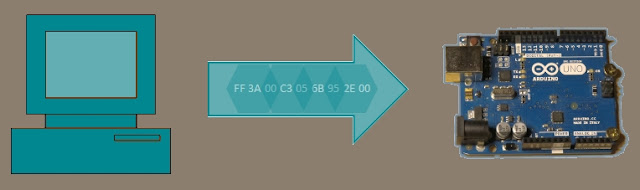
This simple tutorial will show you how to send Hexadecimal values from a computer to an Arduino Uno. The "Processing" programming language will be used to send the HEX values from the computer when a mouse button is pressed. The Arduino will use these values to adjust the brightness of an LED.
Learning Objectives
To Send Hexadecimal (Hex) values from a computer to the Arduino
Trigger an action based on the press of a mouse button
Learn to create a simple Computer to Arduino interface
Use Arduino's PWM capabilities to adjust brightness of an LED
/* ================================================================================================================================================== Project: 5 min tutorial: Send Hex from computer to Arduino Author: Scott C Created: 21th June 2015 Arduino IDE: 1.6.4 Website: http://arduinobasics.blogspot.com/p/arduino-basics-projects-page.html Description: Arduino Sketch used to adjust the brightness of an LED based on the values received on the serial port. The LED needs to be connected to a PWM pin. In this sketch Pin 10 is used, however you could use Pin 3, 5, 6, 9, or 11 - if you are using an Arduino Uno. ===================================================================================================================================================== */
byte byteRead; //Variable used to store the byte received on the Serial Port int ledPin = 10; //LED is connected to Arduino Pin 10. This pin must be PWM capable.
voidsetup() { Serial.begin(9600); //Initialise Serial communication with the computer pinMode(ledPin, OUTPUT); //Set Pin 10 as an Output pin byteRead = 0; //Initialise the byteRead variable to zero. }
voidloop() { if(Serial.available()) { byteRead = Serial.read(); //Update the byteRead variable with the Hex value received on the Serial COM port. }
analogWrite(ledPin, byteRead); //Use PWM to adjust the brightness of the LED. Brightness is determined by the "byteRead" variable. }
Processing Sketch
The latest version of the Processing IDE can be downloaded here.
/* ================================================================================================================================================== Project: 5 min tutorial: Send Hex from computer to Arduino Author: Scott C Created: 21th June 2015 Processing IDE: 2.2.1 Website: http://arduinobasics.blogspot.com/p/arduino-basics-projects-page.html Description: Processing Sketch used to send HEX values from computer to Arduino when the mouse is pressed. The alternating values 0xFF and 0x00 are sent to the Arduino Uno to turn an LED on and off. You can send any HEX value from 0x00 to 0xFF. This sketch also shows how to convert Hex strings to Hex numbers. ===================================================================================================================================================== */
import processing.serial.*; //This import statement is required for Serial communication
Serial comPort; //comPort is used to write Hex values to the Arduino boolean toggle = false; //toggle variable is used to control which hex variable to send String zeroHex = "00"; //This "00" string will be converted to 0x00 and sent to Arduino to turn LED off. String FFHex = "FF"; //This "FF" string will be converted to 0xFF and sent to Arduino to turn LED on.
voidsetup(){ comPort = new Serial(this, Serial.list()[0], 9600); //initialise the COM port for serial communication at a baud rate of 9600. delay(2000); //this delay allows the com port to initialise properly before initiating any communication. background(0); //Start with a black background.
}
voiddraw(){ //the draw() function is necessary for the sketch to compile //do nothing here //even though it does nothing. }
voidmousePressed(){ //This function is called when the mouse is pressed within the Processing window. toggle = ! toggle; //The toggle variable will change back and forth between "true" and "false" if(toggle){ //If the toggle variable is TRUE, then send 0xFF to the Arduino comPort.write(unhex(FFHex)); //The unhex() function converts the "FF" string to 0xFF background(0,0,255); //Change the background colour to blue as a visual indication of a button press. } else { comPort.write(unhex(zeroHex)); //If the toggle variable is FALSE, then send 0x00 to the Arduino background(0); //Change the background colour to black as a visual indication of a button press. } }
The Video
The tutorial above is a quick demonstration of how to convert Hex strings on your computer and send them to an Arduino. The Arduino can use the values to change the brightness of an LED as shown in this tutorial, however you could use it to modify the speed of a motor, or to pass on commands to another module. Hopefully this short tutorial will help you with your project. Please let me know how it helped you in the comments below.
If you like this page, please do me a favour and show your appreciation :
Heart Rate Monitors are very popular at the moment. There is something very appealing about watching the pattern of your own heart beat. And once you see it, there is an unstoppable urge to try and control it. This simple project will allow you to visualize your heart beat, and will calculate your heart rate. Keep reading to learn how to create your very own heart rate monitor.
/* ================================================================================================= Project: Arduino Heart rate monitor Author: Scott C Created: 21st April 2015 Arduino IDE: 1.6.2 Website: http://arduinobasics.blogspot.com/p/arduino-basics-projects-page.html Description: This is a simple sketch that uses a Grove Ear-clip Heart Rate sensor attached to an Arduino UNO, which sends heart rate data to the computer via Serial communication. You can see the raw data using the Serial monitor on the Arduino IDE, however, this sketch was specifically designed to interface with the matching Processing sketch for a much nicer graphical display. NO LIBRARIES REQUIRED. =================================================================================================== */
#define Heart 2 //Attach the Grove Ear-clip sensor to digital pin 2. #define LED 4 //Attach an LED to digital pin 4
boolean beat = false; /* This "beat" variable is used to control the timing of the Serial communication so that data is only sent when there is a "change" in digital readings. */
//==SETUP========================================================================================== voidsetup() { Serial.begin(9600); //Initialise serial communication pinMode(Heart, INPUT); //Set digital pin 2 (heart rate sensor pin) as an INPUT pinMode(LED, OUTPUT); //Set digital pin 4 (LED) to an OUTPUT }
//==LOOP============================================================================================ voidloop() { if(digitalRead(Heart)>0){ //The heart rate sensor will trigger HIGH when there is a heart beat if(!beat){ //Only send data when it first discovers a heart beat - otherwise it will send a high value multiple times beat=true; //By changing the beat variable to true, it stops further transmissions of the high signal digitalWrite(LED, HIGH); //Turn the LED on Serial.println(1023); //Send the high value to the computer via Serial communication. } } else { //If the reading is LOW, if(beat){ //and if this has just changed from HIGH to LOW (first low reading) beat=false; //change the beat variable to false (to stop multiple transmissions) digitalWrite(LED, LOW); //Turn the LED off. Serial.println(0); //then send a low value to the computer via Serial communication. } } }
/* ================================================================================================= Project: Arduino Heart rate monitor Author: Scott C Created: 21st April 2015 Processing IDE: 2.2.1 Website: http://arduinobasics.blogspot.com/p/arduino-basics-projects-page.html Description: A Grove Ear-clip heart rate sensor allows an Arduino UNO to sense your pulse. The data obtained by the Arduino can then be sent to the computer via Serial communication which is then displayed graphically using this Processing sketch. =================================================================================================== */
import processing.serial.*; // Import the serial library to allow Serial communication with the Arduino
int numOfRecs = 45; // numOfRecs: The number of rectangles to display across the screen Rectangle[] myRecs = new Rectangle[numOfRecs]; // myRecs[]: Is the array of Rectangles. Rectangle is a custom class (programmed within this sketch)
Serial myPort; String comPortString="0"; //comPortString: Is used to hold the string received from the Arduino float arduinoValue = 0; //arduinoValue: Is the float variable converted from comPortString boolean beat = false; // beat: Used to control for multiple high/low signals coming from the Arduino
int totalTime = 0; // totalTime: Is the variable used to identify the total time between beats int lastTime = 0; // lastTime: Is the variable used to remember when the last beat took place int beatCounter = 0; // beatCounter: Is used to keep track of the number of beats (in order to calculate the average BPM) int totalBeats = 10; // totalBeats: Tells the computer that we want to calculate the average BPM using 10 beats. int[] BPM = newint[totalBeats]; // BPM[]: Is the Beat Per Minute (BPM) array - to hold 10 BPM calculations int sumBPM = 0; // sumBPM: Is used to sum the BPM[] array values, and is then used to calculate the average BPM. int avgBPM = 0; // avgBPM: Is the variable used to hold the average BPM calculated value.
PFont f, f2; // f & f2 : Are font related variables. Used to store font properties.
//==SETUP============================================================================================== voidsetup(){ size(displayWidth,displayHeight); // Set the size of the display to match the monitor width and height smooth(); // Draw all shapes with smooth edges. f = createFont("Arial",24); // Initialise the "f" font variable - used for the "calibrating" text displayed at the beginning f2 = createFont("Arial",96); // Initialise the "f2" font variable - used for the avgBPM display on screen
for(int i=0; i<numOfRecs; i++){ // Initialise the array of rectangles myRecs[i] = new Rectangle(i, numOfRecs); }
myPort = new Serial(this, Serial.list()[0], 9600); // Start Serial communication with the Arduino using a baud rate of 9600 myPort.bufferUntil('\n'); // Trigger a SerialEvent on new line }
//==DRAW============================================================================================== voiddraw(){ background(0); // Set the background to BLACK (this clears the screen each time) drawRecs(); // Method call to draw the rectangles on the screen drawBPM(); // Method call to draw the avgBPM value to the top right of the screen }
//==drawRecs========================================================================================== void drawRecs(){ // This custom method will draw the rectangles on the screen myRecs[0].setSize(arduinoValue); // Set the first rectangle to match arduinoValue; any positive value will start the animation. for(int i=numOfRecs-1; i>0; i--){ // The loop counts backwards for coding efficiency - and is used to draw all of the rectangles to screen myRecs[i].setMult(i); // setMulti creates the specific curve pattern. myRecs[i].setRed(avgBPM); // The rectangles become more "Red" with higher avgBPM values myRecs[i].setSize(myRecs[i-1].getH()); // The current rectangle size is determined by the height of the rectangle immediately to it's left fill(myRecs[i].getR(),myRecs[i].getG(), myRecs[i].getB()); // Set the colour of this rectangle rect(myRecs[i].getX(), myRecs[i].getY(), myRecs[i].getW(), myRecs[i].getH()); // Draw this rectangle } }
//==drawBPM=========================================================================================== void drawBPM(){ // This custom method is used to calculate the avgBPM and draw it to screen. sumBPM = 0; // Reset the sumBPM variable avgBPM = 0; // Reset the avgBPM variable boolean calibrating = false; // calibrating: this boolean variable is used to control when the avgBPM is displayed to screen
for(int i=1; i<totalBeats; i++){ sumBPM = sumBPM + BPM[i-1]; // Sum all of the BPM values in the BPM array. if(BPM[i-1]<1){ // If any BPM values are equal to 0, then set the calibrating variable to true. calibrating = true; // This will be used later to display "calibrating" on the screen. } } avgBPM = sumBPM/(totalBeats-1); // Calculate the average BPM from all BPM values
fill(255); // The text will be displayed as WHITE text if(calibrating){ textFont(f); text("Calibrating", (4*width)/5, (height/5)); // If the calibrating variable is TRUE, then display the word "Calibrating" on screen fill(0); // Change the fill and stroke to black (0) so that other text is "hidden" while calibrating variable is TRUE stroke(0); } else { textFont(f2); text(avgBPM, (4*width)/5, (height/5)); // If the calibrating variable is FALSE, then display the avgBPM variable on screen stroke(255); // Change the stroke to white (255) to show the white line underlying the word BPM. }
textFont(f); text("BPM", (82*width)/100, (height/11)); // This will display the underlined word "BPM" when calibrating variable is FALSE. line((80*width)/100, (height/10),(88*width)/100, (height/10)); stroke(0); }
//==serialEvent=========================================================================================== void serialEvent(Serial cPort){ // This will be triggered every time a "new line" of data is received from the Arduino comPortString = cPort.readStringUntil('\n'); // Read this data into the comPortString variable. if(comPortString != null) { // If the comPortString variable is not NULL then comPortString=trim(comPortString); // trim any white space around the text. int i = int(map(Integer.parseInt(comPortString),1,1023,1,height)); // convert the string to an integer, and map the value so that the rectangle will fit within the screen. arduinoValue = float(i); // Convert the integer into a float value. if (!beat){ if(arduinoValue>0){ // When a beat is detected, the "trigger" method is called. trigger(millis()); // millis() creates a timeStamp of when the beat occured. beat=true; // The beat variable is changed to TRUE to register that a beat has been detected. } } if (arduinoValue<1){ // When the Arduino value returns back to zero, we will need to change the beat status to FALSE. beat = false; } } }
//==trigger=========================================================================================== void trigger(int time){ // This method is used to calculate the Beats per Minute (BPM) and to store the last 10 BPMs into the BPM[] array. totalTime = time - lastTime; // totalTime = the current beat time minus the last time there was a beat. lastTime = time; // Set the lastTime variable to the current "time" for the next round of calculations. BPM[beatCounter] = 60000/totalTime; // Calculate BPM from the totalTime. 60000 = 1 minute. beatCounter++; // Increment the beatCounter if (beatCounter>totalBeats-1){ // Reset the beatCounter when the total number of BPMs have been stored into the BPM[] array. beatCounter=0; // This allows us to keep the last 10 BPM calculations at all times. } }
//==sketchFullScreen========================================================================================== boolean sketchFullScreen() { // This puts Processing into Full Screen Mode returntrue; }
//==Rectangle CLASS==================================================================================********* class Rectangle{ float xPos, defaultY, yPos, myWidth, myHeight, myMultiplier; // Variables used for drawing rectangles int blueVal, greenVal, redVal; // Variables used for the rectangle colour
Rectangle(int recNum, int nRecs){ // The rectangles are constructed using two variables. The total number of rectangles to be displayed, and the identification of this rectangle (recNum) myWidth = displayWidth/nRecs; // The width of the rectangle is determined by the screen width and the total number of rectangles. xPos = recNum * myWidth; // The x Position of this rectangle is determined by the width of the rectangles (all same) and the rectangle identifier. defaultY=displayHeight/2; // The default Y position of the rectangle is half way down the screen. yPos = defaultY; // yPos is used to adjust the position of the rectangle as the size changes. myHeight = 1; // The height of the rectangle starts at 1 pixel myMultiplier = 1; // The myMultiplier variable will be used to create the funnel shaped path for the rectangles. redVal = 0; // The red Value starts off being 0 - but changes with avgBPM. Higher avgBPM means higher redVal
if (recNum>0){ // The blue Value progressively increases with every rectangle (moving to the right of the screen) blueVal = (recNum*255)/nRecs; } else { blueVal = 0; } greenVal = 255-blueVal; // Initially, the green value is at the opposite end of the spectrum to the blue value. }
void setSize(float newSize){ // This is used to set the new size of each rectangle myHeight=newSize*myMultiplier; yPos=defaultY-(newSize/2); }
void setMult(int i){ // The multiplier is a function of COS, which means that it varies from 1 to 0. myMultiplier = cos(radians(i)); // You can try other functions to experience different effects. }
void setRed(int r){ redVal = int(constrain(map(float(r), 60, 100, 0, 255),0,255)); // setRed is used to change the redValue based on the "normal" value for resting BPM (60-100). greenVal = 255 - redVal; // When the avgBPM > 100, redVal will equal 255, and the greenVal will equal 0. } // When the avgBPM < 60, redVal will equal 0, and greenVal will equal 255.
float getX(){ // get the x Position of the rectangle return xPos; }
float getY(){ // get the y Position of the rectangle return yPos; }
float getW(){ // get the width of the rectangle return myWidth; }
float getH(){ // get the height of the rectangle return myHeight; }
float getM(){ // get the Multiplier of the rectangle return myMultiplier; }
int getB(){ // get the "blue" component of the rectangle colour return blueVal; }
int getR(){ // get the "red" component of the rectangle colour return redVal; }
int getG(){ // get the "green" component of the rectangle colour return greenVal; } }
Processing Code Discussion:
The Rectangle class was created to store relevant information about each rectangle. By using a custom class, we were able to design our rectangles any way we wanted. These rectangles have properties and methods which allow us to easily control their position, size and colour. By adding some smart functionality to each rectangle, we were able to get the rectangle to automatically position and colour itself based on key values.
The Serial library is used to allow communication with the Arduino. In this Processing sketch, the values obtained from the Arduino were converted to floats to allow easy calulations of the beats per minute (BPM). I am aware that I have over-engineered the serialEvent method somewhat, because the Arduino is only really sending two values. I didn't really need to convert the String. But I am happy with the end result, and it does the job I needed it to...
This project is quite simple. I designed it so that you could omit the Processing code if you wanted to. In that scenario, you would only be left with a blinking LED that blinks in time with your pulse. The Processing code takes this project to the next level. It provides a nice animation and calculates the beats per minute (BPM).
I hope you liked this tutorial. Please feel free to share it, comment or give it a plus one. If you didn't like it, I would still appreciate your constructive feedback.
If you like this page, please do me a favour and show your appreciation :
In the previous two parts of the this tutorial, we went through a number of simple sketches to get you acquainted with the way that the Arduino handles various data types when passed through the Serial COM port. Here are the main themes from part ONE:
Stage One: Echoing data with the Arduino
Stage Two: Using Delimiters to split data.
Stage Three:Arduino Maths, simple addition
Stage Four:Sending a double to an Arduino, and then doubling it.
Stage Five:Sending Sensor data from the Arduino to the Serial Monitor
Stage Seven: Arduino and Processing join forces for more fun
Stage Eight: A simple project that shows Serial communication from Arduino to Processing
In Part Three - we will reverse the direction of communication and get Processing to send data to the Arduino via a USB cable,
Stage Nine: A simple processing sketch that switches an LED on the Arduino
Stage Ten: A processing sketch that reads from a text file
Stage Eleven: A processing sketch that reads data from a text file and sends to the Arduino
Stage Twelve: A processing sketch that trasmits data from a file to another Arduino via an XBee module.
Stage Nine - Using your computer to switch an LED
In this stage we create a simple Arduino sketch which will receive a simple command from the Processing Sketch to switch an LED. The Processing sketch will allow you to turn an LED on/off by clicking on the Processing Application window. It will detect the press of the mouse, and will send a command to the Arduino via the USB Serial COM port.
/* ===================================================
Simple number reader: Written by ScottC - 07 Apr 2013
 Arduino Version: 1.04
======================================================*/

// The onboard LED is on pin # 13
int onboardLED = 13;


void setup() {
 // Begin Serial communication
 Serial.begin(9600);

 //Set the onboard LED to OUTPUT
 pinMode(onboardLED, OUTPUT);
}

void loop(){
 /* Read serial port, if the number is 0, then turn off LED
 if the number is 1 or greater, turn the LED on. */
 while (Serial.available() > 0) {
 int num=Serial.read()-'0';
 if(num<1){
 digitalWrite(onboardLED, LOW); //Turn Off LED
 } else{
 digitalWrite(onboardLED, HIGH); //Turn On LED
 }
 }
}
/*===========================================================
 Toggle Switch: Send Number to Arduino
 Written by Scott C on 07 Apr 2013
 Processing Version: 2.0b8
=============================================================*/

import processing.serial.*;

Serial comPort;
boolean ledState=false; //LED is off

void setup(){
 //Open COM Port for Communication
 comPort = new Serial(this, Serial.list()[0], 9600);
 background(255,0,0); //Start with a Red background
}

void draw(){
}


void mousePressed() {
 //Toggle led ON and OFF
 ledState=!ledState;

 //If ledState is True - then send a value=1 (ON) to Arduino
 if(ledState){
 background(0,255,0); //Change the background to green

 /*When the background is green, transmit
 a value=1 to the Arduino to turn ON LED */
 comPort.write('1');
 }else{
 background(255,0,0); //Change background to red
 comPort.write('0'); //Send "0" to turn OFF LED.
 }
}
The Video
Stage Ten: Reading from a Text File
We are now going to give the Arduino a rest (for a moment) and concentrate on a Processing Sketch that will read from a text file. Once we learn this skill, we can then build this Processing functionality into our Arduino Projects. Reading from a text file in Processing is actually quite easy if you use the loadStrings()method. However, it is best if you make things easy for yourself by using delimiters. The most common delimitter is a "comma". The comma allows the computer to group information according to your needs.
11,22,33,44,55,66
1,1,2,2,3,3,4,4,5,5,6,6
112,223,334,455,566
The examples above contain the same numbers but are delimitted in different ways. We are going to import a few different numbers/letters and store them in an array. We will then iterate through the array to display the values within. So let us now create the text file. Copy and paste the following text into notepad and save the file, but remember where you save it, because we will need to know location and the name of the file in order to read from in.
Copy and Paste into Notepad:
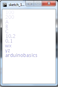
100,200,A,B,C,10.2,0.1,wx,yz,arduinobasics
Save the file I am going to call my file data.txt, and will be saving it to my D drive, so the file will be located here:
D:/data.txt
We will now create the processing sketch to read the text file and display the data on the screen. We will use the comma delimiters to separate the data so that it displays in the following way:
/* =============================================================
 ReadTextFile and Display on Screen:
 Written by ScottC on 15th April 2013 using
 Processing version 2.0b8

 Website: http://arduinobasics.blogspot.com/
 Projects: http://arduinobasics.blogspot.com/p/arduino-basics-projects-page.html

 References:
 Displaying Text: http://processing.org/reference/text_.html
 Reading Text File: http://processing.org/reference/loadStrings_.html
=================================================================*/

void setup(){
 size(180,250);
 background(255);

 /* Read the text file */
 String[] lines = loadStrings("D:/data.txt");
 int numOfLines=lines.length;
 for(int i=0;i<numOfLines;i++){

 /* Split the data based on a "," delimiter. */
 String[] data = splitTokens(lines[i], ",");
 int dataCount = data.length;

 for(int j=0; j<dataCount; j++){
 /* Set the size and colour of the text */
 textSize(16);
 fill(100,100,255,50+(j*20));

 /* Display the text on the screen */
 text(data[j],10,16+(16*j));
 }
 }
}


void draw(){
}
The code above has the ability to display data from multiple lines within the text file, however for simplicity, I have chosen to use a single line. If I wanted to display more than one line, I would have to change the "for-loops".
Stage Eleven: Read Text File and send to Arduino
In stage 10 we used the Processing programming language to import a line of data from a text file, break-up the line into pieces (based on comma delimiters) and then displayed the data on the Computer Screen. We will now use this knowledge and take it one step further. We will create a text file, import the data using processing, but this time we will send the data to the Arduino. Meanwhile the Arduino will be waiting patiently for this data, and once it receives the data, it will react according to our needs. We are going to keep this simple. The goal is to send two different letters from the Computer to the Arduino. One letter will turn an LED on, and the other letter will turn the LED off. We will also send an integer to tell the Arduino how long to keep the LED on or off.
GOAL: Turn an LED on and off by reading a text file.
Our first step in this process is to create a text file that will store our important data. We will store two variables in this file. The first variable will be used to tell the Arduino whether we want to turn the LED on or whether we want to turn the LED off. We will use the letter "O" to turn the LED on, and use the letter "X" to turn the LED off. The second variable will be a time based variable. It will be used to tell the Arduino "how long" to keep the LED on or off. We will store this variable as an integer and will represent time in "milliseconds".
1000 milliseconds = 1 second
It makes sense to keep these two variables as a pair, however we will separate them using a comma delimitter. We will separate each command by putting the variables on a new line. Copy and paste the following data into notepad (or equivalent text editor), and save the file to your harddrive. I have saved this file as
D:/LEDdata.txt
Text File Data:Here is the data to put into your text file (notepad):
/* Read TextFile Data: Written by ScottC on 24 April 2013
 Arduino IDE version: 1.0.4
 http://arduinobasics.blogspot.com.au/2013/04/serial-communication-tutorial-part-3.html
*/

/* Global Variables */
byte byteRead; //Used to receive data from computer.
int timeDelay; //time that the LED is On or Off
int maxtimeDelay=10000; //Maximum time delay = 10 seconds
int ledPin=13; //LED connected to pin 13 on Arduino UNO.

void setup() {
//Set pin 13 (ledPin) as an output
 pinMode(ledPin, OUTPUT);
// Turn the Serial Protocol ON
 Serial.begin(9600);
}

void loop() {
 /* check if data has been sent from the computer: */
 if (Serial.available()) {
 /* read the most recent byte */
 byteRead = Serial.read();

 switch (byteRead) {
 case 69: //This is an enquiry, send an acknowledgement
 Serial.println("A");
 break;
 case 79: //This is an "O" to turn the LED on
 digitalWrite(ledPin, HIGH);
 break;
 case 88: //This is an "X" to turn the LED off
 digitalWrite(ledPin, LOW);
 break;
 case 46: //End of line
 //Make sure time delay does not exceed maximum.
 if(timeDelay > maxtimeDelay){
 timeDelay=maxtimeDelay;
 }
 //Set the time for LED to be ON or OFF
 delay(timeDelay);
 Serial.println("S");
 timeDelay=0; //Reset timeDelay;
 break;
 default:
 //listen for numbers between 0-9
 if(byteRead>47 && byteRead<58){
 //number found, use this to construct the time delay.
 timeDelay=(timeDelay*10)+(byteRead-48);
 }
 }
 }
}
Our next step is to import the data in the text file into Processing and then send the data to the Arduino. You may want to review Stage 10 of this tutorial for another example of importing text file data into Processing. You may also want to review stage 7 which shows how to receive data from an Arduino. We will import all of the data from the file when we push a button on the Processing Window, and send this data to the Arduino via the USB cable that is connected to the computer. We are going to use the same COM port that the Computer uses to upload Arduino Sketches, therefore it is important that you close the Arduino Serial Monitor before you run the processing sketch, otherwise you will get an error which states that the COM port is not available.
/* TextFile Data sender (Stage 11) Written by ScottC on 24th April 2013 using Processing Version 2.0b8 The full tutorial can be found here: http://arduinobasics.blogspot.com/2013/04/serial-communication-tutorial-part-3.html */
import processing.serial.*;
Serial comPort; //The com port used between the computer and Arduino int counter=0; // Helps to keep track of values sent. int numItems=0; //Keep track of the number of values in text file String comPortString; //String received From Arduino String textFileLines[]; //Array of text file lines String lineItems[]; //Array of line items
void setup(){ comPort = new Serial(this, Serial.list()[0], 9600); //Setup the COM port comPort.bufferUntil('\n'); //Generate a SerialEvent when a newline is received background(255,0,0); //Start with a Red background }
/* Draw method is not used in this sketch */ void draw(){ }
//When the mouse is pressed, write an "E" to COM port. //The Arduino should send back an "A" in return. This will //generate a serialEvent - see below. void mousePressed() { comPort.write("E"); }
/*If the String received = A, then import the text file change the background to Green, and start by sending the first line of the text file to the Arduino */ if(comPortString.equals("A")){ textFileLines=loadStrings("D:/LEDdata.txt"); background(0,255,0); sendLineNum(counter); }
/*If the the String received = S, then increment the counter which will allow us to send the next line in the text file. If we have reached the end of the file, then reset the counter and change the background colour back to red. */ if(comPortString.equals("S")){ counter++; if(counter > (textFileLines.length-1)){ background(255,0,0); counter=0; } else { sendLineNum(counter); } } } }
/*The sendLineNum method is used to send a specific line from the imported text file to the Arduino. The first line item tells the Arduino to either switch the LED on or off. The second line item, tells the Arduino how long to keep the LED on or off. The full-stop is sent to the Arduino to indicate the end of the line. */
I need to finish my XBee tutorial before doing this stage. But am just about to start studying again. So this stage probably won't get completed for another couple of months. But I hope there is enough content to keep you satisfied for the time being.
Description: Serial Communication Tutorial (Part 3)
Rating: 3.5
Reviewer: Unknown
ItemReviewed: Serial Communication Tutorial (Part 3)


 The Arduino Sketch
 The Processing Sketch
 Copy and Paste into Notepad: