.
Nextion Enhanced Stepper Motor Piano Project Reviewed by Unknown on 09:12 Rating: 4.5

Nextion Enhanced Stepper Motor Piano Project


Introduction


Nextion is a programmable human machine interface (HMI) that can be customized and designed to simplify the interaction between you and your project.
This Nextion Enhanced module (NX4827K043) with a resistive touch screen display, has some additional features not seen in previous traditional versions of the Nextion series.

  • A built in real time clock (RTC)
  • Accessible flash memory (32MB)
  • GPIO functionality
  • Faster clock speed

Before you connect the Nextion Enhanced module to your project, you need to design your interface with the free Nextion Editor. The editor can be downloaded here.
In this project, I will be designing a simple dynamic interface, which will allow me to interact with a stepper motor in two different ways.
The first interface will let me control the direction and speed of the stepper motor through the use of a simple GUI. I will have left and right arrows for the direction, and up and down arrows for the speed. I will also map the Expansion board to this interface for a more tactile experience.
The second interface will be more musical in nature. I will design a functional “Stepper motor piano” that will allow me to play simple songs using the rotational sounds of the stepper motor. This concept is not new, but I will show you how easy it is to make.


Project Scope


My project will show a splash screen when the project is powered up. After 3 seconds, the first interface will display.
The first interface will have 4 arrows:

  1. Left and Right arrows for the stepper motor direction of rotation
  2. Up and down arrows to increase/decrease stepper motor rotational speed
  3. Next Page button – to jump to the next interface

Each arrow/button on the first interface will be mapped to a specific button on the expansion board. Eg.

  1. Left/Right arrow is mapped to Left/Right button
  2. Up/Down arrow is mapped to Up/Down button
  3. Next page button is mapped to Enter button on the expansion board

The second interface will look like a piano on the Nextion Enhanced display. Each key on the piano will transmit a specific and unique number to the Arduino.
The specific number received by the Arduino will allow it to set the speed of stepper motor which will ultimately affect the frequency of sound it produces. Therefore when the “C” key is pressed on the Nextion display, the stepper motor will rotate at a frequency that sounds like a “C” note.
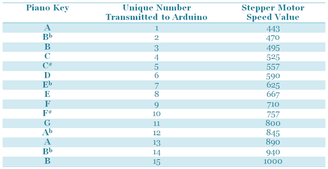
Table describes the stepper motor speed value and the number that is transmitted to the Arduino for each piano key


The stepper motor speeds can be determined by tuning the motor to specific notes using the first interface and an iPhone app called Tuner T1 Free".
If you plan to replicate this project, you will need to determine the relevant speeds of your own stepper motor, and substitute your values into the Arduino code later on in this tutorial.


Create a New Project


The first step is to create the interfaces in the Nextion Editor on your PC. You can download the Nextion Editor here.. Load up the Nextion Editor and create a new project.
When you start a new project, you need to make sure that you select the correct Nextion device from the available options.
I am using the “Nextion Enhanced NX4827K043” device.

  1. Select File → New
  2. Select a name for the project and save it to a suitable place on the hard drive
  3. Select the appropriate Nextion device from the available options
    1. My device has a screen size of 480 x 272 pixels
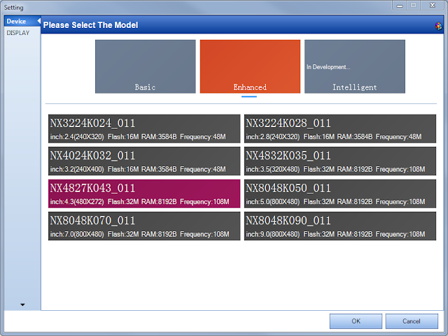

Selection of the NX4827K043_011 module from other available selections


Project Resources


You need to import all of the resources (eg. pictures and fonts) into your project, and then design the interface to suit your specific needs.

Fonts


I will not be using any fonts in my project, but if you wanted to write any text to the display, you will need to generate a font in the Nextion Editor.

  1. Tools → Font Generator
    1. Select the Height of the Font (eg. 16)
    2. Select the Font code type (eg. iso-8859-2)
    3. Select if you want it to be in Bold or not
    4. Choose the Font you want to use (eg. Arial)
    5. Choose the spacing (eg. 0)
    6. And finally give this Font a unique name (e.g. Arial_16)
    7. Push the “Generate Font” button on the bottom right of the window


Dialog box for the font generator in the Nextion Editor

Once you press the Generate Font button, it will get you to save the font using a *.zi extension, and will automatically ask you if you would like to “Add the generated font?” to the project. If you are happy with the font, and would like to use this font in your project, then select “Yes”, otherwise select “No” and start again.

Font generator acknowledgement, dialog box

You cannot add any text to your project until you have imported or added a font. All of your project fonts will be displayed in the fonts window.

A list of available fonts in the Nextion editor (arduinobasics.blogspot.com)

Each font will automatically be indexed, so that you can reference the font programmatically if required. In fact all resources that you add to your project are assigned a number and incremented by one for every resource added. For some resources, you can see this number to the left of the item. E.g. In the picture above, the Courier Font has an index of 0, whereas the Arial font has an index of 1. If you delete a resource, the index number may change for that item.


Pictures


As I said before, I will not be using any fonts for my project because the words on the screen will not be changing in any way. I can get away with designing a “Picture” and importing that into the project. I will need 3 pictures for my project.

  1. Splash screen
  2. Stepper Motor Controller
  3. Stepper Motor Piano

On the Nextion Enhanced NX4827K043 device, each picture must be

  • 480 x 272 pixels in size

We will now import the following pictures into the Nextion Editor so that we can use them in the project.
In the bottom left hand corner of the Nextion editor is the “Fonts and Picture” resource window:

  1. Select the Picture tab
  2. Then select the “+” icon
  3. This will open a dialog box to allow you to select the picture(s) to add to the project. You can select more than one picture to import.

I imported the following pictures from my computer:


Splash Screen



ArduinoBasics Splash Screen image (arduinobasics.blogspot.com)


Interface 1: Stepper Motor Controller
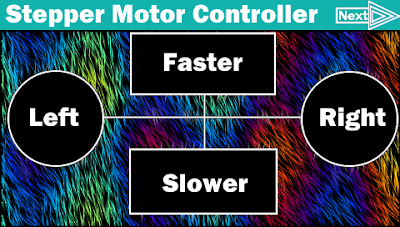


Stepper Motor Controller Background Image for Interface (arduinobasics.blogspot.com)


Interface 2: Stepper Motor Piano


Stepper Motor Piano Background Image for Interface 2 (arduinobasics.blogspot.com)


Creating the GUI


Pages


Every resource will get an ID based on the order it is added, and each resource will automatically get a name. You can change the name of the resource or object, but you cannot edit the ID.
Three pages will be designed to meet the criteria described above.
To add a page, you simply select the “Add” icon from the “page window”. And keep adding pages until you have a total of 3 pages (page0, page1 and page2).
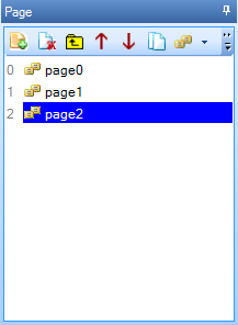
Add pages to the project in the Nextion Editor (arduinobasics.blogspot.com)


Page 0 - Splash Screen


When the Nextion is powered up, the splash screen will be displayed for 3 seconds before it shows the Stepper Motor Controller screen. I used the following steps to create the splash screen.

  1. Add the splash screen picture to page0
    1. Select “page0” from the Page window
    2. Select “Picture” from the Toolbox window
    3. Double-click the “pic” attribute from the Attribute window
    4. Select the splash screen image from the list
    5. Press the OK button
  2. Add a Timer to page0
    1. Select Timer from the Toolbox window
    2. Change the “tim” attribute from 400 to 3000 in the Attribute window
    3. Enter “page page1” in the User code section of the Timer Event(0)

This timer event will make the Nextion jump to page1 after 3 seconds.
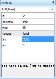
Attributes of the Timer Event in the Nextion Editor (arduinobasics.blogspot.com)


Page 1 - Stepper Motor Controller


This page is designed to control the direction and speed of the stepper motor.
There will be two buttons for the direction (Left and Right), and two buttons for the speed (Faster and Slower). And one more button to jump to the next page (i.e. the Stepper Motor Piano page). These buttons will also be mapped to the Nextion expansion board. The tactile buttons of the expansion board will provide an alternative method of controlling the motor.

  1. Add the Stepper Motor Controller picture to page1
    1. Select “page1” from the Page window
    2. Select “Picture” from the Toolbox window
    3. Double-click the “pic” attribute from the Attribute window
    4. Select the “Stepper Motor Controller” image from the list
    5. Press the OK button
  2. Add Hotspots over each button on the Stepper Motor Controller image
    1. Select “Hotspot” from the Toolbox window
    2. Drag and resize the Hotspot so that it covers the “Left” button
      1. This is the area that will respond to “Left button” presses.
      2. It will be transparent when uploaded to the Nextion board
    3. Select the “Touch Press Event” tab in the Event window
    4. Un-Check the “Send Component ID” checkbox
    5. Type the following code into the “User Code” Section of the Event window:
      • print “L”
    6. Change the object name of the hotspot to “Left” using the following process:
      1. Select objname from the attribute window and change the text from “m0” to “Left”
      2. It is not compulsory to change the hotspot object name; however it will help later on.
    7. Repeat steps 2a-2f for each of the other buttons in the following order and as per the table below
      1. Right
      2. Faster
      3. Slower
      4. Next

Shows how to program each button on the first inteface of this project in the Nextion Editor (arduinobasics.blogspot.com)

The decimal ASCII code for the letter “L” is 76, hence when the Nextion Enhanced display sends the letter L to the Arduino using the print “L” command, the Arduino will receive the number 76. When the right button is pressed, it will receive the number 82, and so on.
The “Next” button does not transmit anything to the Arduino, it is simply there to jump to the next interface on the Nextion Enhanced display, hence the reason why the user code is different for that button.
  1. Map the buttons to the Expansion board
    1. Select “page0” and then “page1” from the Page window

    2. Select Page 1 in the Nextion Editor (arduinobasics.blogspot.com)

    3. Select the “Preinitialize Event” tab from the Event window
    4. Enter the following code into the “User Code” field of the Preinitialize Event tab:
      • cfgpio 5,1,Left
      • cfgpio 2,1,Right
      • cfgpio 4,1,Faster
      • cfgpio 3,1,Slower
      • cfgpio 1,1,Next

User code for the preinitialize event box in page1 (arduinobasics.blogspot.com)

Please note: There is one space between cfgpio and the number next to it, but there are no other spaces on each line. If you introduce extra spaces, it will not compile.
This code maps the buttons on the expansion board to the hotspot objects on page1. For example, when the Left button (IO5) on the expansion board is pressed, it simulates the actions or events associated with hotspot m0/Left. In this case it will send a value of “L” (76) to the Arduino.

Expansion Board Buttons (arduinobasics.blogspot.com)

The IO number is marked within brackets on the expansion board.
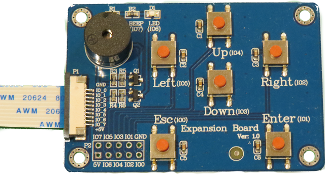
Expansion Board (arduinobasics.blogspot.com)


Page 2 - Stepper Motor Piano


This interface will be designed to look like a piano, and will allow me to control the stepper motor such that it produces a note in the same key as the one I press on the Nextion display. The stepper motor will produce the note by rotating at a specific frequency.

  1. Add the Stepper Motor Piano picture to page2
    1. Select “page2” from the Page window
    2. Select “Picture” from the Toolbox window
    3. Double-click the “pic” attribute from the Attribute window
    4. Select the “Stepper Motor Piano” image from the list
    5. Press the OK button
  2. Add Hotspots over each key on the Stepper Motor Piano image
    1. Select “Hotspot” from the Toolbox window
    2. Drag and resize the Hotspot so that it covers the the “A” key.
      1. This is the area that will respond to “A-key” presses.
      2. It will be transparent when uploaded to the Nextion board
    3. Select the “Touch Press Event” tab in the Event window
    4. Type the following into the “User Code” section
      • print 1
    5. Repeat steps 2a-2d for each of the other keys as per the table below
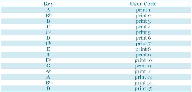
The User code for each key in interface two (arduinobasics.blogspot.com)

When the specific key is pressed, the Nextion Enhanced board will transmit the printed number, followed by three 0x00 values. The terminating values can be ignored.
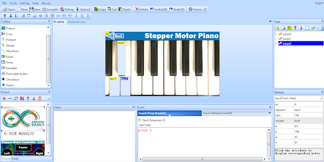
Designing the second interface in the Nextion Editor (arduinobasics.blogspot.com)

  1. The “Back” button will allow me to jump back to the previous interface on the Nextion Enhanced board.
    1. Create a hotspot for the back button using the following process:
      1. Select Hotspot from the Toolbox window
      2. Move/Resize the hotspot over the “Back” button
    2. Select the Event window
    3. Make sure the “Touch press event” tab is selected
    4. Type:   page page1   into the User Code section


Debugging


The good thing about the Nextion Editor, is that you can test out the interface functionality before uploading it to the board.

Nextion Editor Menu Items (arduinobasics.blogspot.com)


  1. Save the project by pressing the save button on the task bar
  2. Then press the compile button
  3. Then press the debug button.

A Nextion emulator window will appear. This window should respond in the same manner as Nextion module after the Nextion file is uploaded to the board. This emulator is a great way to test out your interface and to make sure it looks and works as expected. Once I was happy with the interface(s), I transferred the compiled Nextion file onto an SD card:

  1. Press the compile button
  2. File → Open Build Folder
  3. Select the *.tft file with the same name as that of the project
  4. Copy it to a micro SDHC card
  5. Insert the SDHC card into the SD card slot on the Nextion display
  6. Power up the Nextion board

Wait for the file to flash the Nextion board, and you should see a message that looks like this:
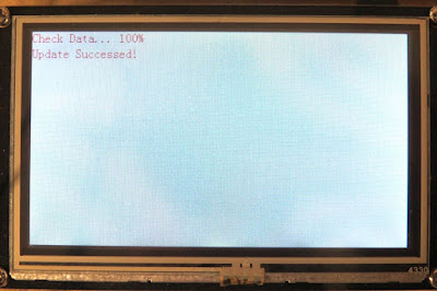
The message displayed after successful flashing of the Nextion board (arduinobasics.blogspot.com)

The next step is to power off the Nextion board, and remove the SDHC card.


ARDUINO SETUP


The Nextion Enhanced display is ready, and now it is the Arduino’s turn. The Arduino is programmed to receive Serial messages from the Nextion Enhanced display and control the stepper motor based on the letters or numbers received. The unique letters or numbers being transmitted from the Nextion board, allow the Arduino to understand what button is being pressed, and it uses those numbers or letters to control the flow of code in order to perform specific stepper motor actions.


Arduino Libraries and IDE


The Arduino IDE can be downloaded from this site.
The SoftwareSerial library is used to enable Serial communication between the Arduino and the Nextion Enhanced display.
The AccelStepper library is used to simplify the process of stepper motor control.


ARDUINO CODE:


Here is the Arduino Code for this project:
I set up a maximum and minimum speed for the motors, and some pre-defined keys. It is possible to “tune” the motor using the first interface of the Nextion display. You can do this by making the motor turn faster or slower until you reach the desired key.
I used the “Tuner T1 Free” app from the iTunes app store to identify WHEN the motor was producing a note in key.
When the motor was producing a specific note, I would write down the stepper motor speed that was printed to the Serial monitor window. Every time the motor speed is increased or decreased, the Arduino code prints the speed to the serial monitor window. I then use these speeds to update the notes[] array in the Arduino code.
The notes[] array holds the stepper motor speeds that correspond to the individual notes on the piano. The Nextion display essentially sends the index number of the note to play from the notes array on the Arduino, thereby simplifying the code required to spin the motor at 16 different speeds.


Hooking it up:


With all boards powered off, the next step is to make all of the necessary hardware connections to the Arduino. There are two major sections to consider,

  1. The Stepper motor driver and motor
  2. The Nextion Enhanced board

You need to ensure that you use an external power source to power both the stepper motor and the Nextion Enhanced board. The stepper motor driver board itself was powered by the Arduino without any problems, but the actual stepper motor will need an external power supply. The Nextion Enhanced board also needs an external power supply because it requires more current than the Arduino can safely provide.
Here is how you would connect the Arduino to the Stepper motor driver board and associated stepper motor.

Connecting up the stepper motor to the Arduino via a Stepper motor controller (arduinobasics.blogspot.com)


Connection Table showing connections between the Arduino and the Steppr motor via a Stepper motor controller (arduinobasics.blogspot.com)


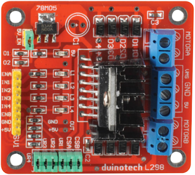
Duinotech L298 module (arduinobasics.blogspot.com)


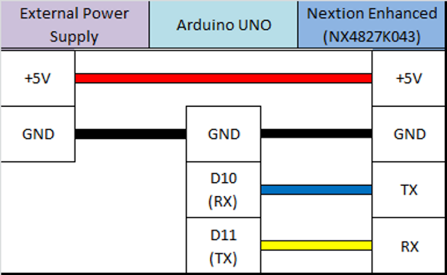
And this is how you would connect the Arduino to the Nextion Enhanced display

Diagram showing the connections between the Arduino and the Nextion Enhanced Module (arduinobasics.blogspot.com)


Table that shows the connection between the Arduino UNO and the Nextion Enhanced NX4827K043 module


Nextion Enhanced module and Expansion Board (arduinobasics.blogspot.com)


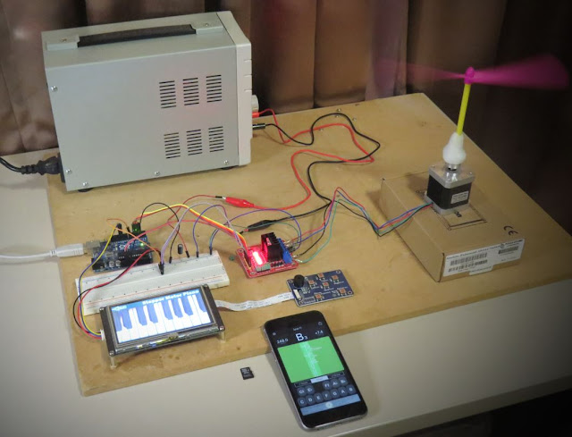
And this is what it looked like when I put it all together:

All the connections required for the stepper motor piano project (arduinobasics.blogspot.com)


Picture showing the complete setup of the Nextion Enhanced Stepper motor piano project (arduinobasics.blogspot.com)


Make note of the external power supply used. I made sure that I had a large enough power supply to handle the power requirements of the project, and utilized the relevant datasheets to help me identify those requirements. If you plan to replicate this project, make sure you take into consideration the specific power requirements of your motor, your motor driver and your Nextion display. The Arduino can only supply 400mA of current from the 5V pin.
With everything hooked up, I powered up the Nextion display, then powered up the Arduino. The stepper motor starts spinning automatically. I used the first interface to change the direction and/or speed of the motor. Please note the maximum and minimum speeds set up in the Arduino code.
I then used the Next button to jump to the second interface on the Nextion Enhanced display. The second interface looks like a piano. And when I press a key on the piano display, the motor changes speed to match the note I pressed.
Voila !! The stepper motor piano is born !!
I played a number of simple tunes on the Stepper motor piano and was surprised how well it worked. Very clever !!


Concluding comments


This project is relatively simple, but stepper motors can be tricky to set up and tune. Nothing a bit of determination cannot fix.
This project was a lot of fun. If you plan to replicate this project, I would be interested to see your versions, or just knowing if this helped you in any way.


iTead Studio Logo


This project would not have been possible without the collaborative efforts of iTead Studio. Their Nextion Enhanced display has a lot more to offer than what I have shown you here. But hopefully this tutorial gives you some insight into the power of such a display, and perhaps how it could improve the project you are currently working on. The only thing I did not like was the power requirements. I would have preferred something within Arduino power supply limits. Nevertheless, I am very happy with the Nextion Enhanced display, and would recommend it to anyone looking for a Human Machine interface to include in their project. You can see how simple it was to create TWO interfaces for my project, and I only scratched the surface.
Description: Nextion Enhanced Stepper Motor Piano Project Rating: 3.5 Reviewer: Unknown ItemReviewed: Nextion Enhanced Stepper Motor Piano Project
Hacking Robotic Arm using Controllino and Cayenne Reviewed by Unknown on 13:08 Rating: 4.5

Hacking Robotic Arm using Controllino and Cayenne


Description

This tutorial will show you how to take over the controls of the OWI Robotic Arm with the help of an Arduino compatible, open-source PLC called the Controllino MAXI, together with Cayenne (my go-to iOT application for remote connection to my Arduino projects). The Controllino MAXI will provide the physical connections to the OWI robotic arm, and Cayenne will allow me to control the arm via my web browser or via the Cayenne app on my phone.


Arduino Libraries and IDE

  1. The Arduino IDE can be used to program the Controllino. You can dowload the Arduino IDE from here: https://www.arduino.cc/en/main/software.
  2. You will also need to read the Cayenne Ethernet library installation instructions in order to install the Cayenne Ethernet Library.
  3. The Controllino will connect to the internet via the Ethernet port onboard.
  4. You do not need the Controllino library for this project, however, if you have a Controllino, you might as well install the library. You can read the Controllino library installation instructions from their GitHub webpage here: https://github.com/CONTROLLINO-PLC/CONTROLLINO_Library.
  5. You will need to notify the Arduino IDE of the Controllino MAXI board by pasting the supplied URL into the "Additional Boards Manager URLs" in the Arduino IDE.

  6. This is located under: FILE - PREFERENCES - Additional Boards Manager URLs.
  7. The URL that you need to paste is in STEP 3 of the Controllino Library installation instructions on their GitHub page.
  8. The video at the top of this tutorial may help clarify the process.


ARDUINO CODE:

The code above is very simple, however you will need to create a dashboard of widgets from within your Cayenne account in order to control the OWI robotic Arm from your phone or via the Dashboard webpage.


Setting up Cayenne Dashboard

Once you have created your Cayenne account, you will be presented with a webpage to choose a board to connect to. Controllino is an Arduino compatible PLC, so make sure to follow these instructions for setting up the Controllino in your Cayenne Account.

  1. Select Arduino from the available list of boards.
  2. Make sure to install the necessary libraries if your have not done so already.
  3. Select Arduino MEGA from the avaliable list of Arduino boards
  4. Select Ethernet Shield W5100
  5. Copy and paste the Arduino code that pops up on screen into your Arduino IDE and upload to the Controllino.
  6. Alternatively, copy and paste the code from above, however you will need to insert your Authentication token to get it to work

After you upload the code to the Controllino, and providing it has an ethernet cable connected to the internet router (and has access to the internet), and is powered on, it will connect to your Cayenne Dashboard. You can now add widgets to the dashboard in real time to interact with the Controllino, and without uploading any more code to the open source PLC.


Adding Widgets

We need to add a number of widgets in order to activate the relays on the Controllino. The relavent digital pins that we will need to know about can be found on the Controllino website here: https://controllino.biz/downloads/.

Here is the direct link to the PINOUT file for the Controllino MAXI.

"Armed" with that knowledge, we can now create the widgets which are necessary to control the relays on the Controllino. From within the Cayenne dashboard, please follow these instructions to create a widget:

  1. Select - ADD NEW
  2. Select - DEVICE/WIDGET
  3. Select - ACTUATORS
  4. Then - RELAY from the dropdown box
  5. Select - RELAY SWITCH
  6. Give the widget a descriptive name to differentiate it from the other widgets and a name that is somewhat informative (eg. R0 - Pos)
  7. I gave the first widget the name "R0 - Pos", because it will connect to Relay R0, and that relay will be connected to the Positive (POS) terminal of the OWI robotic arm.
  8. Select the device you would like to connect to. Be aware that you can change the name of the device in the settings. If you followed this tutorial, it should have the name "Arduino MEGA", but I changed the name of the device to "Controllino" to be more accurate.
  9. We will be using a digital pin to control the relay, therefore select "Digital" as the Connectivity option
  10. For this specific widget, we will be controlling R0, which is activated by digital pin D22 on the Controllino. Therefore select "D22" from the "Pin" dropdown box.
  11. Choose a "Button" as the widget type
  12. Choose an icon from the dropdown box that makes sense to you
  13. Skip Step 1
  14. Select Step 2: Add actuator

You should now see your new widget on the dashboard. Select the widget to enable or activate that relay. If you do this, and if everything goes to plan, you will see the LED for R0 illuminate on the Controllino. You now have to add the rest of the widgets to the dashboard in order to control the rest of the relays on the Controllino.


Widget Dashboard

Here is a table to show you how I setup my dashboard.


Fritzing diagram


OWI Robotic Arm Pins


Normal OWI Robotic Arm Circuit

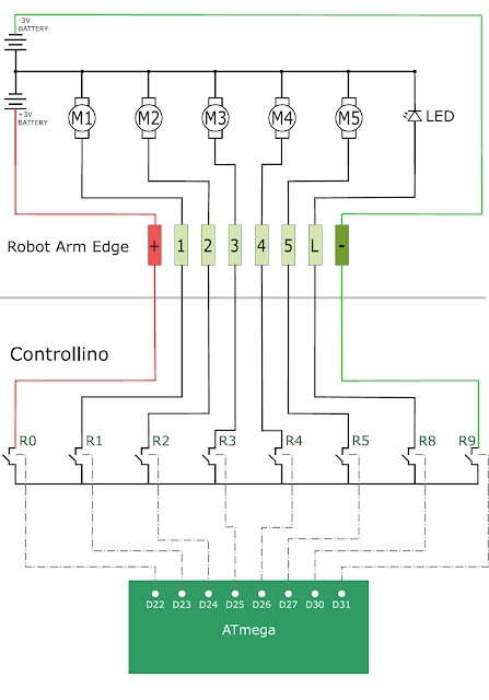
The following circuit diagram will show you how the wired control box is normally connected to the OWI Robotic arm. This is the circuit diagram of the OWI robotic arm under normal operating contidtions.


OWI Robotic Arm Circuit when connected to Controllino

The following circuit diagram will show you how the OWI Robotic Arm will be controlled by the relays of the Controllino. This is the circuit diagram of the OWI robotic arm when it is connected to the Controllino.


All connected

The OWI Robotic Arm is connected to a breadboard using the female-to-male jumper wires. Solid core wire is then fed through to the relay terminals of the Controllino. You could just wire it up so that the robotic arm is connected directly to the Controllino, however, I did not have the right connectors for this purpose.
The Controllino is also connected to my internet router via a normal RJ-45 ethernet cable, and is powered by a 12V DC power adapter.


Summary

Now that you have all the physical connections made, uploaded the code to the Controllino, and have created your dashboard in Cayenne, you should be able to control your OWI Robotic arm from anywhere in the world. As demonstrated in the video at the start of this tutorial, the robotic arm has quite a bit of give on each of the joints, which makes it difficult to achieve certain tasks that require an element of precision. There goes that idea of being able to perform surgery with this thing !!! At least you can get it to make you a cup of tea, and if you are patient enough, you might even get a grape once in a while.

Thank you to Controllino and Cayenne for making this tutorial possible. If you would like your product featured in my tutorials, please contact me on my contact page.


If you like this page, please do me a favour and show your appreciation :

 
Visit my ArduinoBasics Google + page.
Follow me on Twitter by looking for ScottC @ArduinoBasics.
I can also be found on Pinterest and Instagram.
Have a look at my videos on my YouTube channel.

Description: Hacking Robotic Arm using Controllino and Cayenne Rating: 3.5 Reviewer: Unknown ItemReviewed: Hacking Robotic Arm using Controllino and Cayenne
Prextron CHAIN BLOCKS - Arduino Nano controlled Ultrasonic sensor that switches a motor wirelessly using 433MHz RF modules and a relay board. Reviewed by Unknown on 09:01 Rating: 4.5

Prextron CHAIN BLOCKS - Arduino Nano controlled Ultrasonic sensor that switches a motor wirelessly using 433MHz RF modules and a relay board.


Description

In this tutorial, I will be evaluating Prextron CHAIN blocks – a new system that allows you to connect your sensors and actuators to an Arduino NANO using clever 3D-printed prototyping boards that can be stacked sideways. This very modular system makes it easy to connect, disconnect and replace project components, and eliminate the “rats nest of wires” common to many advanced Arduino projects. CHAIN BLOCKS are open, which means that you can incorporate any of your sensors or actuators to these prototyping boards, and you can decide which specific pin on Arduino you plan to use. The CHAIN BLOCK connections prevent or reduce common connection mistakes, which make them ideal for class-room projects and learning activities.

I am going to set up a project to put these CHAIN BLOCKs to the test:
When I place my hand in-front of an Ultrasonic sensor, the Arduino will transmit a signal wirelessly to another Arduino, and consequently turn on a motor.


Parts Required:

You need the following Prextron Chain Blocks


Please note: You may need to solder the module wires to the CHAIN BLOCK protoboard.


Arduino Libraries and IDE

This project does not use any libraries. However, you will need to upload Arduino code to the Arduino. For this you will need the Arduino IDE which can be obtained from the official Arduino website:
https://www.arduino.cc/en/main/software


ARDUINO CODE: RF Transmitter


ARDUINO CODE: RF Receiver


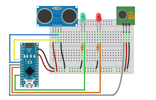
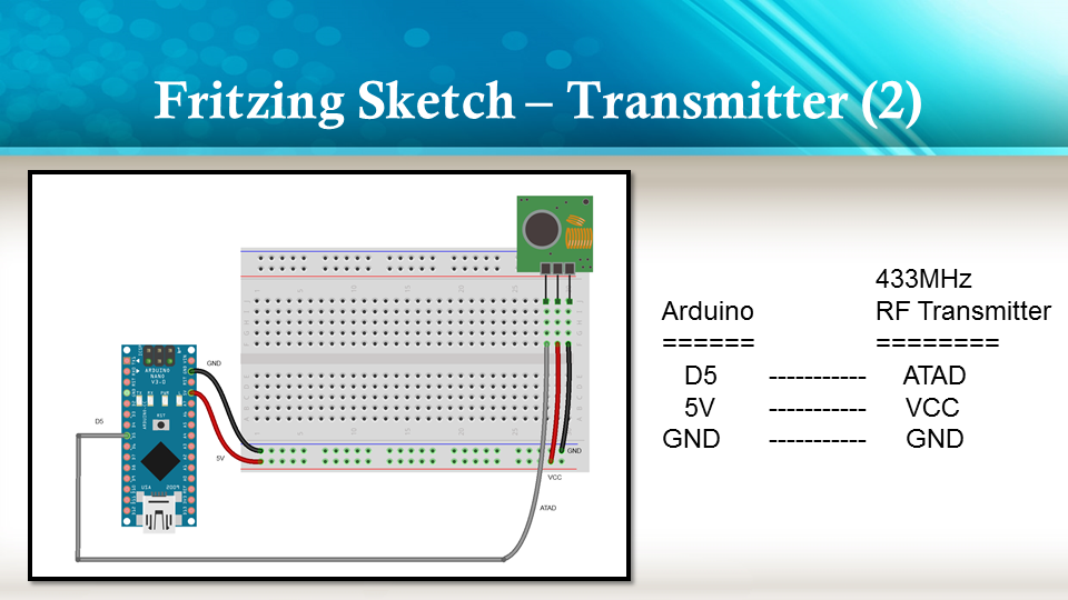
Fritzing diagrams for Transmitter


Fritzing diagrams for Receiver


Concluding comments

The purpose of this project was to evaluate Prextron CHAIN BLOCKs and put them to the test. Here is what I thought of CHAIN BLOCKS at the time of evaluation. Some of my points mentioned below may no longer apply to the current product. It may have evolved / improved since then. So please take that into consideration


What I liked about Chain Blocks

  • The design is simple, the product is simple.
  • Once the Chain Blocks were all assembled, they were very easy to connect to each other.
  • I can really see the benefit of Chain Blocks in a teaching environment, because it simplifies the connection process, and reduces connection mixups.
  • It was good to see that the blocks come in different colours, which means that you can set up different colour schemes for different types of modules.
  • You can incorporate pretty much any sensor or Actuator into the Chain block which is very appealing.
  • You also have the flexibility of choosing which pins you plan to use on the Arduino.
  • Projects look a lot neater, because you no longer have the rats nest of wires.
  • The Blocks lock into each other which means that they are much easier to transport/carry.


What I did not like about Chain Blocks

  • In most cases, the Chain Block protoboard lanes were not numbered, which increased the chances of making mistakes when soldering
  • The need to solder modules to the protoboard, may be a discouragement for some people.
  • I would have liked a choice of different size Chain blocks. Some of the sensors did not fit nicely into the Square blocks.
  • Prextron really need to work on their website if they plan to get serious with this product: Webpage has incomplete functionality or irrelevant links etc etc.


Thank you very much to Prextron for providing the CHAIN BLOCKS used in this tutorial, and allowing me to try out their product. If you are interested in trying them yourself, then make sure to visit them at:


If you like this page, please do me a favour and show your appreciation :

 
Visit my ArduinoBasics Google + page.
Follow me on Twitter by looking for ScottC @ArduinoBasics.
I can also be found on Pinterest and Instagram.
Have a look at my videos on my YouTube channel.

Description: Prextron CHAIN BLOCKS - Arduino Nano controlled Ultrasonic sensor that switches a motor wirelessly using 433MHz RF modules and a relay board. Rating: 3.5 Reviewer: Unknown ItemReviewed: Prextron CHAIN BLOCKS - Arduino Nano controlled Ultrasonic sensor that switches a motor wirelessly using 433MHz RF modules and a relay board.
Garage Door Monitor with Cayenne Reviewed by Unknown on 17:14 Rating: 4.5

Garage Door Monitor with Cayenne


Description

Using the HMC5883L magnetometer sensor of the GY-80 module from ICStation to monitor a garage door and notify when it has been opened or closed. The Cayenne service provides much of the monitoring and notifying functionality. A major feature of this project. Cayenne takes care of all of the complicated work behind the scenes, making it easy to connect your Arduino to the cloud and allow you to monitor your garage from virtually anywhere.
 
This project was created specifically to monitor a garage, but you will soon discover that this project could be used to monitor a whole host of other things. Monitor your front door, your back door, your bag, your chair, your cookie jar.
 
Monitor for peace of mind, or catch someone in the act of stealing your stuff. This project has got you covered. Let's see how:


HMC5883L DataSheet:

You can find the datasheet for the HMC5883L pretty easily by searching on the internet.
HMC5883L datasheet - Sparkfun


Arduino Libraries and IDE

Here is a link to the Arduino IDE download. The IDE is required to upload code to the Seeeduino Cloud.

You need the Cayenne Library installed in your Arduino IDE.
You can find the Cayenne library here:
Cayenne Libarary
 
There are libraries on the internet for the GY-80 module, however, it is relatively easy to use the magnetometer on this module. And therefore no libraries are required for the sensor. If you would like some more information about using the magnetometer sensor, and how to get the most out of it, then please have a look at my previous tutorial which goes into much more detail.


ARDUINO CODE:


You need to make sure to insert your OWN Cayenne token into the sketch above. You will get this token when connecting your Arduino to the Cayenne service. Watch the video for further explanation.


Fritzing diagram

Cayenne Widgets

Please make sure to watch the video to see how to connect the Seeeduino Cloud to Cayenne and how to create the Cayenne widgets. Cayenne widgets are necessary to create the dashboard on your phone or browser. They will also interact with the Arduino sketch, and will also be involved in creating the notification system. The following links will take you to the relevant part of the video:

The Master switch button is used to switch monitoring from OFF to ON (and vice versa). Therefore you can choose when to monitor the garage and when to stop monitoring. When first installing the project onto your garage door, and turning the Seeeduino Cloud on, it will automatically calibrate each sensor to a value of 1000.
 
If you experience any drift away from 1000 for whatever reason, simply press the Request calibration button, and each sensor will be recalibrated back to 1000. The x,y and z axis widgets are there so that you can see the readings coming from the magnetometer sensor. And when any of the axis variables breach the threshold away from 1000, it will trigger the Door Status widget. This is how we can tell if the door is open or closed.
 
We also use the Door Status widget to help with the notification system. When the Door status changes from "Closed" to "Open", a notification trigger will be activated, and a message will be sent via email or SMS. This notification is useful for monitoring when the door was opened. If you happen to recalibrate when the door is open. You will get a notification when the garage door closes.


Concluding comments

This project is relatively simple, and quite easy to set up. What I liked about this project was the versatility and alternate uses. You can use the same setup to monitor many different things. It is not just limited to monitoring a garage door. But being able to tell whether my garage door is opened or closed, especially after I have driven away from my house , is really cool. Now I don't have to drive all the way back home to check. Let me know if you have replicated this project, and also what kinds of things you decided to monitor with this project.

Description: Garage Door Monitor with Cayenne Rating: 3.5 Reviewer: Unknown ItemReviewed: Garage Door Monitor with Cayenne
Back to top