Prextron CHAIN BLOCKS - Arduino Nano controlled Ultrasonic sensor that switches a motor wirelessly using 433MHz RF modules and a relay board.
Reviewed by Unknown on
09:01
Rating: 4.5
In this tutorial, I will be evaluating Prextron CHAIN blocks – a new system that allows you to connect your sensors and actuators to an Arduino NANO using clever 3D-printed prototyping boards that can be stacked sideways. This very modular system makes it easy to connect, disconnect and replace project components, and eliminate the “rats nest of wires” common to many advanced Arduino projects. CHAIN BLOCKS are open, which means that you can incorporate any of your sensors or actuators to these prototyping boards, and you can decide which specific pin on Arduino you plan to use. The CHAIN BLOCK connections prevent or reduce common connection mistakes, which make them ideal for class-room projects and learning activities.
I am going to set up a project to put these CHAIN BLOCKs to the test: When I place my hand in-front of an Ultrasonic sensor, the Arduino will transmit a signal wirelessly to another Arduino, and consequently turn on a motor.
Please note: You may need to solder the module wires to the CHAIN BLOCK protoboard.
Arduino Libraries and IDE
This project does not use any libraries. However, you will need to upload Arduino code to the Arduino. For this you will need the Arduino IDE which can be obtained from the official Arduino website: https://www.arduino.cc/en/main/software
ARDUINO CODE: RF Transmitter
ARDUINO CODE: RF Receiver
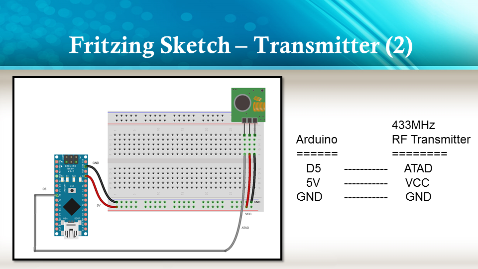
Fritzing diagrams for Transmitter
Fritzing diagrams for Receiver
Concluding comments
The purpose of this project was to evaluate Prextron CHAIN BLOCKs and put them to the test. Here is what I thought of CHAIN BLOCKS at the time of evaluation. Some of my points mentioned below may no longer apply to the current product. It may have evolved / improved since then. So please take that into consideration
What I liked about Chain Blocks
The design is simple, the product is simple.
Once the Chain Blocks were all assembled, they were very easy to connect to each other.
I can really see the benefit of Chain Blocks in a teaching environment, because it simplifies the connection process, and reduces connection mixups.
It was good to see that the blocks come in different colours, which means that you can set up different colour schemes for different types of modules.
You can incorporate pretty much any sensor or Actuator into the Chain block which is very appealing.
You also have the flexibility of choosing which pins you plan to use on the Arduino.
Projects look a lot neater, because you no longer have the rats nest of wires.
The Blocks lock into each other which means that they are much easier to transport/carry.
What I did not like about Chain Blocks
In most cases, the Chain Block protoboard lanes were not numbered, which increased the chances of making mistakes when soldering
The need to solder modules to the protoboard, may be a discouragement for some people.
I would have liked a choice of different size Chain blocks. Some of the sensors did not fit nicely into the Square blocks.
Prextron really need to work on their website if they plan to get serious with this product: Webpage has incomplete functionality or irrelevant links etc etc.
Thank you very much to Prextron for providing the CHAIN BLOCKS used in this tutorial, and allowing me to try out their product. If you are interested in trying them yourself, then make sure to visit them at:
If you like this page, please do me a favour and show your appreciation :
Description: Prextron CHAIN BLOCKS - Arduino Nano controlled Ultrasonic sensor that switches a motor wirelessly using 433MHz RF modules and a relay board.
Rating: 3.5
Reviewer: Unknown
ItemReviewed: Prextron CHAIN BLOCKS - Arduino Nano controlled Ultrasonic sensor that switches a motor wirelessly using 433MHz RF modules and a relay board.
Sonar Project Tutorial
Reviewed by Unknown on
00:05
Rating: 4.5
This project utilises the HC-SR04 ultrasonic sensor to scan for nearby objects. You can program the Arduino to sound an alarm when the sensor detects an object within a specific vicinity. Connecting it to a computer allows data to be plotted to make a simple sonar scanner. The scanning ability is made possible through the use of a hobby servo motor SG-5010, and an Adafruit motor shield v1.0. This project could easily be extended to provide object avoidance for any robotics project. This tutorial was designed so that you could see how the components interact, and also to see how you can use and expand the functionality of the motor shield.
Gauge parts: Paper (to print the face of the gauge), and some glue to stick it to the wood. MDF Standard panel (3mm width) - for the top and base of the gauge, and the pointer. Galvanized bracket (25x25x40mm) Timber screws: Hinge-long threads csk head Phillips drive (4G x 12mm) Velcro dots - to allow temporary application of the mini-breadboard to the gauge.
The gauge was used as a customisable housing for the Arduino and related parts, and to provide some visual feedback of the servo position.
Part of the sketch above was created using Fritzing.
The Servo motor can be connected to either of the Servo motor pins (Digital 9 or 10). In this case, the Servo is attached to digital pin 10.Make sure you read the servo motor data sheet and identify the VCC (5V), GND, and Signal connectors. Not all servos have the same colour wires. My servo motor has a white signal wire, a red VCC wire and a black GND wire.
Also when connecting your wires to the HC-SR04, pay attention to the front of the sensor. It will identify the pins for you. Make sure you have the sensor facing the correct way. In this sketch, the sensor is actually facing towards you.
In this sketch - we connect the Echo pin to Analog pin 0 (A0). Trigger pin to Analog pin 1 (A1) VCC to a 5V line/pin and GND to a GND line/pin
Pay attention to your motor shield, I have seen some pictures on the internet where the 5V and GND are reversed.
Arduino Code: You can download the Arduino IDE from this site.
/* ArduinoBasics: Sonar Project - Created by Scott C on 10 Jan 2013 http://arduinobasics.blogspot.com/2013/01/arduino-basics-sonar-project-tutorial.html This project uses the Adafruit Motor shield library (copyright Adafruit Industries LLC, 2009 this code is public domain, enjoy!) The HC-SR04 sensor uses some code from the following sources: From Virtualmix: http://goo.gl/kJ8Gl Modified by Winkle ink here: http://winkleink.blogspot.com.au/2012/05/arduino-hc-sr04-ultrasonic-distance.html And modified further by ScottC here: http://arduinobasics.blogspot.com/ on 10 Nov 2012. */
#include <AFMotor.h> #include <Servo.h>
// DC hobby servo Servo servo1;
/* The servo minimum and maximum angle rotation */ staticconstint minAngle = 0; staticconstint maxAngle = 176; int servoAngle; int servoPos; int servoPin = 10;
/* Define pins for HC-SR04 ultrasonic sensor */ #define echoPin A0 // Echo Pin = Analog Pin 0 #define trigPin A1 // Trigger Pin = Analog Pin 1 #define LEDPin 13 // Onboard LED long duration; // Duration used to calculate distance long HR_dist=0; // Calculated Distance int HR_angle=0; // The angle in which the servo/sensor is pointing int HR_dir=1; // Used to change the direction of the servo/sensor int minimumRange=5; //Minimum Sonar range int maximumRange=200; //Maximum Sonar Range
/*--------------------SETUP()------------------------*/ void setup() { //Begin Serial communication using a 9600 baud rate Serial.begin (9600);
// Tell the arduino that the servo is attached to Digital pin 10. servo1.attach(servoPin);
//Setup the trigger and Echo pins of the HC-SR04 sensor pinMode(trigPin, OUTPUT); pinMode(echoPin, INPUT); pinMode(LEDPin, OUTPUT); // Use LED indicator (if required) }
/* check if data has been sent from the computer: */ if (Serial.available()) {
/* This expects an integer from the Serial buffer */ HR_angle = Serial.parseInt();
/* If the angle provided is 0 or greater, then move servo to that position/angle and then get a reading from the ultrasonic sensor */ if(HR_angle>-1){ /*Make sure that the angle provided does not go beyond the capabilities of the Servo. This can also be used to calibrate the servo angle */ servoPos = constrain(map(HR_angle, 0,180,minAngle,maxAngle),minAngle,maxAngle); servo1.write(servoPos);
/* Call the getDistance function to take a reading from the Ultrasonic sensor */ getDistance(); } } }
/*--------------------getDistance() FUNCTION ---------------*/ void getDistance(){
/* The following trigPin/echoPin cycle is used to determine the distance of the nearest object by bouncing soundwaves off of it. */ digitalWrite(trigPin, LOW); delayMicroseconds(2);
//Calculate the distance (in cm) based on the speed of sound. HR_dist = duration/58.2;
/*Send the reading from the ultrasonic sensor to the computer */ if (HR_dist >= maximumRange || HR_dist <= minimumRange){ /* Send a 0 to computer and Turn LED ON to indicate "out of range" */ Serial.println("0"); digitalWrite(LEDPin, HIGH); } else { /* Send the distance to the computer using Serial protocol, and turn LED OFF to indicate successful reading. */ Serial.println(HR_dist); digitalWrite(LEDPin, LOW); } }
Servo Angles: You will notice on line 22, the maximum servo angle used was 176. This value was obtained through trial and error (see below).
Calibrating the servo angles You may need to calibrate your servo in order to move through an angle of 0 to 180 degrees without straining the motor. Go to line 21-22 and change the minAngle to 0 and the maxAngle to 180. Once you load the sketch to the Arduino/Freetronics ELEVEN, you can then open the Serial Monitor and type a value like 10 <enter>, and then keep reducing it until you get to 0. If you hear the servo motor straining, then move it back up to a safe value and change the minimum servo angle to that value. Do the same for the maximum value.
In this example, the servo's minAngle value was 0, and maxAngle value was 176 after calibration, however, as you can see from the video, the physical range of the servo turned out to be 0 to 180 degrees.
The Processing Sketch You can download the Processing IDE from this site.
/* Created by ScottC on 10 Jan 2013 http://arduinobasics.blogspot.com/2013/01/arduino-basics-sonar-project-tutorial.html */
import processing.serial.*;
int distance; int angle=0; int direction=1;
int[] alphaVal = newint[100]; // used to fade the lines int[] distance2 = newint[100]; // used to store the line lengths int lineSize = 4; // line length multiplier (makes it longer)
String comPortString; Serial comPort;
/*---------------------SETUP---------------------------*/ void setup( ) { size(displayWidth,displayHeight); //allows fullscreen view smooth(); background(0); // set the background to black
/*Open the serial port for communication with the Arduino Make sure the COM port is correct - I am using COM port 8 */ comPort = new Serial(this, "COM8", 9600); comPort.bufferUntil('\n'); // Trigger a SerialEvent on new line
/*Initialise the line alphaValues to 0 (ie not visible) */ for(int i=0; i<91; i++){ alphaVal[i] = 0; } }
/*---------------------DRAW-----------------*/ void draw( ) { background(0); //clear the screen
/*Draw each line and dot */ for(int i=0; i<91; i++){
/*Gradually fade each line */ alphaVal[i]=alphaVal[i]-4;
/*Once it gets to 0, keep it there */ if(alphaVal[i]<0){ alphaVal[i]=0; }
/*The colour of the line will change depending on the distance */ stroke(255,distance2[i],0,alphaVal[i]);
/* Use a line thickness of 2 (strokeweight) to draw the line that fans out from the bottom center of the screen. */ strokeWeight(2); line(width/2, height, (width/2)-cos(radians(i*2))*(distance2[i]*lineSize), height-sin(radians(i*2))*(distance2[i]*lineSize));
/* Draw the white dot at the end of the line which does not fade */ stroke(255); strokeWeight(1); ellipse((width/2)-cos(radians(i*2))*(distance2[i]*lineSize), height-sin(radians(i*2))*(distance2[i]*lineSize),5,5); } }
/* A mouse press starts the scan. There is no stop button */ void mousePressed(){ sendAngle(); }
/*When the computer receives a value from the Arduino, it will update the line positions */ void serialEvent(Serial cPort){ comPortString = cPort.readStringUntil('\n'); if(comPortString != null) { comPortString=trim(comPortString);
/* Use the distance received by the Arduino to modify the lines */ distance = int(map(Integer.parseInt(comPortString),1,200,1,height)); drawSonar(angle,distance);
/* Send the next angle to be measured by the Arduino */ sendAngle(); } }
/*---------------------------sendAngle() FUNCTION----------------*/ void sendAngle(){ //Send the angle to the Arduino. The fullstop at the end is necessary. comPort.write(angle+".");
/*Increment the angle for the next time round. Making sure that the angle sent does not exceed the servo limits. The "direction" variable allows the servo to have a sweeping action.*/ angle=angle+(2*direction); if(angle>178||angle<1){ direction=direction*-1; } }
/*-----------------sketchFullScreen(): Allows for FullScreen view------*/ boolean sketchFullScreen() { returntrue; }
/*----------------- drawSonar(): update the line/dot positions---------*/ void drawSonar(int sonAngle, int newDist){ alphaVal[sonAngle/2] = 180; distance2[sonAngle/2] = newDist; }
The HC-SR04 Ultrasonic Sensor is a very affordable proximity/distance sensor that has been used mainly for object avoidance in various robotics projects . It essentially gives your Arduino eyes / spacial awareness and can prevent your robot from crashing or falling off a table. It has also been used in turret applications, water level sensing, and even as a parking sensor. This simple project will use the HC-SR04 sensor with an Arduino and a Processing sketch to provide a neat little interactive display on your computer screen.
Parts Required: Freetronics Eleven or any compatible Arduino. HC-SR04 Ultrasonic Sensor Mini Breadboard 4.5cm x 3.5cm Protoshieldand female header pins (not essential - but makes it more tidy) Wiresto connect it all together
/* HC-SR04 Ping distance sensor: VCC to arduino 5v GND to arduino GND Echo to Arduino pin 7 Trig to Arduino pin 8 This sketch originates from Virtualmix: http://goo.gl/kJ8Gl Has been modified by Winkle ink here: http://winkleink.blogspot.com.au/2012/05/arduino-hc-sr04-ultrasonic-distance.html And modified further by ScottC here: http://arduinobasics.blogspot.com.au/2012/11/arduinobasics-hc-sr04-ultrasonic-sensor.html on 10 Nov 2012. */
int maximumRange = 200; // Maximum range needed int minimumRange = 0; // Minimum range needed long duration, distance; // Duration used to calculate distance
void setup() { Serial.begin (9600); pinMode(trigPin, OUTPUT); pinMode(echoPin, INPUT); pinMode(LEDPin, OUTPUT); // Use LED indicator (if required) }
void loop() { /* The following trigPin/echoPin cycle is used to determine the distance of the nearest object by bouncing soundwaves off of it. */ digitalWrite(trigPin, LOW); delayMicroseconds(2);
//Calculate the distance (in cm) based on the speed of sound. distance = duration/58.2;
if (distance >= maximumRange || distance <= minimumRange){ /* Send a negative number to computer and Turn LED ON to indicate "out of range" */ Serial.println("-1"); digitalWrite(LEDPin, HIGH); } else { /* Send the distance to the computer using Serial protocol, and turn LED OFF to indicate successful reading. */ Serial.println(distance); digitalWrite(LEDPin, LOW); }
/* The following Processing Sketch was created by ScottC on the 10 Nov 2012 : http://arduinobasics.blogspot.com/ Inspired by this Processing sketch by Daniel Shiffman: http://processing.org/learning/basics/sinewave.html */ import processing.serial.*;
int numOfShapes = 60; // Number of squares to display on screen int shapeSpeed = 2; // Speed at which the shapes move to new position // 2 = Fastest, Larger numbers are slower
//Global Variables Square[] mySquares = new Square[numOfShapes]; int shapeSize, distance; String comPortString; Serial myPort;
/* -----------------------Setup ---------------------------*/ void setup(){ size(displayWidth,displayHeight); //Use entire screen size. smooth(); // draws all shapes with smooth edges.
/* Calculate the size of the squares and initialise the Squares array */ shapeSize = (width/numOfShapes); for(int i = 0; i<numOfShapes; i++){ mySquares[i]=new Square(int(shapeSize*i),height-40); }
/*Open the serial port for communication with the Arduino Make sure the COM port is correct - I am using COM port 8 */ myPort = new Serial(this, "COM8", 9600); myPort.bufferUntil('\n'); // Trigger a SerialEvent on new line }
/* ------------------------Draw -----------------------------*/ void draw(){ background(0); //Make the background BLACK delay(50); //Delay used to refresh screen drawSquares(); //Draw the pattern of squares }
/* Use the distance received by the Arduino to modify the y position of the first square (others will follow). Should match the code settings on the Arduino. In this case 200 is the maximum distance expected. The distance is then mapped to a value between 1 and the height of your screen */ distance = int(map(Integer.parseInt(comPortString),1,200,1,height)); if(distance<0){ /*If computer receives a negative number (-1), then the sensor is reporting an "out of range" error. Convert all of these to a distance of 0. */ distance = 0; } } }
/* Set the Y position of the 1st square based on sensor value received */ mySquares[0].setY((height-shapeSize)-distance);
/* Update the position and colour of each of the squares */ for(int i = numOfShapes-1; i>0; i--){ /* Use the previous square's position as a target */ targetY=mySquares[i-1].getY(); oldY=mySquares[i].getY();
if(abs(oldY-targetY)<2){ newY=targetY; //This helps to line them up }else{ //calculate the new position of the square newY=oldY-((oldY-targetY)/shapeSpeed); } //Set the new position of the square mySquares[i].setY(newY);
/*Calculate the colour of the square based on its position on the screen */ blueVal = int(map(newY,0,height,0,255)); redVal = 255-blueVal; fill(redVal,0,blueVal);
/* Draw the square on the screen */ rect(mySquares[i].getX(), mySquares[i].getY(),shapeSize,shapeSize); } }
/* ---------------------sketchFullScreen---------------------------*/ // This puts processing into Full Screen Mode boolean sketchFullScreen() { returntrue; }
/* ---------------------CLASS: Square ---------------------------*/ classSquare{ int xPosition, yPosition;