My attention is drawn towards the noise behind me.... I cannot believe it. There it is.
The Arduino is taking a SELFIE !!
How did this happen?
Well actually, it is not that difficult for an Arduino.
I found out that my Canon Powershot SX50 HS camera has a port on the side for a remote switch. In the "Optional Accessories" section of the camera brochure, it identifies the remote switch model as RS-60E3. I then looked up the model number on this website to find out the size of the jack (3 core, 2.5mm), and the pinout (Ground, focus and shutter) required to emulate the remote switch. Once I had this information, I was able to solder some really long wires to the jack and connect up the circuit (as described below).
And before I knew it, the Arduino was taking Selfies !!!
Warning : Any circuit you build for your camera (including this one) is at your own risk. I will not take responsibility for any damage caused to any of your equipment.
/* =============================================================== Project: Arduino Selfie Author: Scott C Created: 14th Sept 2014 Arduino IDE: 1.0.5 Website: http://arduinobasics.blogspot.com/p/arduino-basics-projects-page.html Description: Arduino takes selfie every 30 seconds ================================================================== */
/* Connect 5V on Arduino to VCC on Relay Module Connect GND on Arduino to GND on Relay Module */
#define CH1 8 // Connect Digital Pin 8 on Arduino to CH1 on Relay Module #define CH3 7 // Connect Digital Pin 7 on Arduino to CH3 on Relay Module
voidsetup(){ //Setup all the Arduino Pins pinMode(CH1, OUTPUT); pinMode(CH3, OUTPUT);
//Turn OFF any power to the Relay channels digitalWrite(CH1,LOW); digitalWrite(CH3,LOW); delay(2000); //Wait 2 seconds before starting sequence }
voidloop(){ digitalWrite(CH1, HIGH); //Focus camera by switching Relay 1 delay(2000); digitalWrite(CH1, LOW); //Stop focus delay(100); digitalWrite(CH3, HIGH); //Press shutter button for 0.5 seconds delay(500); digitalWrite(CH3,LOW); //Release shutter button delay(30000); //Wait 30 seconds before next selfie }
By connecting up the camera to an Arduino, the camera just got smarter !! The Arduino connects to 2 different channels on the relay board in order to control the focus and the shutter of the camera. The relays are used to isolate the camera circuit from that of the Arduino. I have also included a couple of diodes and resistors in the circuit as an extra precaution, however they may not be needed.
Warning : Any circuit you build for your camera (including this one) is at your own risk. I will not take responsibility for any damage caused to any of your equipment. Do your research, and take any precautions you see fit.
The Video
If you like this page, please do me a favour and show your appreciation :
In the previous two parts of the this tutorial, we went through a number of simple sketches to get you acquainted with the way that the Arduino handles various data types when passed through the Serial COM port. Here are the main themes from part ONE:
Stage One: Echoing data with the Arduino
Stage Two: Using Delimiters to split data.
Stage Three:Arduino Maths, simple addition
Stage Four:Sending a double to an Arduino, and then doubling it.
Stage Five:Sending Sensor data from the Arduino to the Serial Monitor
Stage Seven: Arduino and Processing join forces for more fun
Stage Eight: A simple project that shows Serial communication from Arduino to Processing
In Part Three - we will reverse the direction of communication and get Processing to send data to the Arduino via a USB cable,
Stage Nine: A simple processing sketch that switches an LED on the Arduino
Stage Ten: A processing sketch that reads from a text file
Stage Eleven: A processing sketch that reads data from a text file and sends to the Arduino
Stage Twelve: A processing sketch that trasmits data from a file to another Arduino via an XBee module.
Stage Nine - Using your computer to switch an LED
In this stage we create a simple Arduino sketch which will receive a simple command from the Processing Sketch to switch an LED. The Processing sketch will allow you to turn an LED on/off by clicking on the Processing Application window. It will detect the press of the mouse, and will send a command to the Arduino via the USB Serial COM port.
/* ===================================================
Simple number reader: Written by ScottC - 07 Apr 2013
 Arduino Version: 1.04
======================================================*/

// The onboard LED is on pin # 13
int onboardLED = 13;


void setup() {
 // Begin Serial communication
 Serial.begin(9600);

 //Set the onboard LED to OUTPUT
 pinMode(onboardLED, OUTPUT);
}

void loop(){
 /* Read serial port, if the number is 0, then turn off LED
 if the number is 1 or greater, turn the LED on. */
 while (Serial.available() > 0) {
 int num=Serial.read()-'0';
 if(num<1){
 digitalWrite(onboardLED, LOW); //Turn Off LED
 } else{
 digitalWrite(onboardLED, HIGH); //Turn On LED
 }
 }
}
/*===========================================================
 Toggle Switch: Send Number to Arduino
 Written by Scott C on 07 Apr 2013
 Processing Version: 2.0b8
=============================================================*/

import processing.serial.*;

Serial comPort;
boolean ledState=false; //LED is off

void setup(){
 //Open COM Port for Communication
 comPort = new Serial(this, Serial.list()[0], 9600);
 background(255,0,0); //Start with a Red background
}

void draw(){
}


void mousePressed() {
 //Toggle led ON and OFF
 ledState=!ledState;

 //If ledState is True - then send a value=1 (ON) to Arduino
 if(ledState){
 background(0,255,0); //Change the background to green

 /*When the background is green, transmit
 a value=1 to the Arduino to turn ON LED */
 comPort.write('1');
 }else{
 background(255,0,0); //Change background to red
 comPort.write('0'); //Send "0" to turn OFF LED.
 }
}
The Video
Stage Ten: Reading from a Text File
We are now going to give the Arduino a rest (for a moment) and concentrate on a Processing Sketch that will read from a text file. Once we learn this skill, we can then build this Processing functionality into our Arduino Projects. Reading from a text file in Processing is actually quite easy if you use the loadStrings()method. However, it is best if you make things easy for yourself by using delimiters. The most common delimitter is a "comma". The comma allows the computer to group information according to your needs.
11,22,33,44,55,66
1,1,2,2,3,3,4,4,5,5,6,6
112,223,334,455,566
The examples above contain the same numbers but are delimitted in different ways. We are going to import a few different numbers/letters and store them in an array. We will then iterate through the array to display the values within. So let us now create the text file. Copy and paste the following text into notepad and save the file, but remember where you save it, because we will need to know location and the name of the file in order to read from in.
Copy and Paste into Notepad:
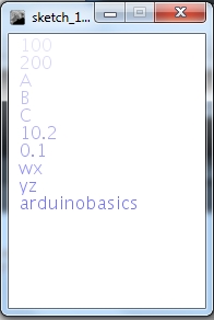
100,200,A,B,C,10.2,0.1,wx,yz,arduinobasics
Save the file I am going to call my file data.txt, and will be saving it to my D drive, so the file will be located here:
D:/data.txt
We will now create the processing sketch to read the text file and display the data on the screen. We will use the comma delimiters to separate the data so that it displays in the following way:
/* =============================================================
 ReadTextFile and Display on Screen:
 Written by ScottC on 15th April 2013 using
 Processing version 2.0b8

 Website: http://arduinobasics.blogspot.com/
 Projects: http://arduinobasics.blogspot.com/p/arduino-basics-projects-page.html

 References:
 Displaying Text: http://processing.org/reference/text_.html
 Reading Text File: http://processing.org/reference/loadStrings_.html
=================================================================*/

void setup(){
 size(180,250);
 background(255);

 /* Read the text file */
 String[] lines = loadStrings("D:/data.txt");
 int numOfLines=lines.length;
 for(int i=0;i<numOfLines;i++){

 /* Split the data based on a "," delimiter. */
 String[] data = splitTokens(lines[i], ",");
 int dataCount = data.length;

 for(int j=0; j<dataCount; j++){
 /* Set the size and colour of the text */
 textSize(16);
 fill(100,100,255,50+(j*20));

 /* Display the text on the screen */
 text(data[j],10,16+(16*j));
 }
 }
}


void draw(){
}
The code above has the ability to display data from multiple lines within the text file, however for simplicity, I have chosen to use a single line. If I wanted to display more than one line, I would have to change the "for-loops".
Stage Eleven: Read Text File and send to Arduino
In stage 10 we used the Processing programming language to import a line of data from a text file, break-up the line into pieces (based on comma delimiters) and then displayed the data on the Computer Screen. We will now use this knowledge and take it one step further. We will create a text file, import the data using processing, but this time we will send the data to the Arduino. Meanwhile the Arduino will be waiting patiently for this data, and once it receives the data, it will react according to our needs. We are going to keep this simple. The goal is to send two different letters from the Computer to the Arduino. One letter will turn an LED on, and the other letter will turn the LED off. We will also send an integer to tell the Arduino how long to keep the LED on or off.
GOAL: Turn an LED on and off by reading a text file.
Our first step in this process is to create a text file that will store our important data. We will store two variables in this file. The first variable will be used to tell the Arduino whether we want to turn the LED on or whether we want to turn the LED off. We will use the letter "O" to turn the LED on, and use the letter "X" to turn the LED off. The second variable will be a time based variable. It will be used to tell the Arduino "how long" to keep the LED on or off. We will store this variable as an integer and will represent time in "milliseconds".
1000 milliseconds = 1 second
It makes sense to keep these two variables as a pair, however we will separate them using a comma delimitter. We will separate each command by putting the variables on a new line. Copy and paste the following data into notepad (or equivalent text editor), and save the file to your harddrive. I have saved this file as
D:/LEDdata.txt
Text File Data:Here is the data to put into your text file (notepad):
/* Read TextFile Data: Written by ScottC on 24 April 2013
 Arduino IDE version: 1.0.4
 http://arduinobasics.blogspot.com.au/2013/04/serial-communication-tutorial-part-3.html
*/

/* Global Variables */
byte byteRead; //Used to receive data from computer.
int timeDelay; //time that the LED is On or Off
int maxtimeDelay=10000; //Maximum time delay = 10 seconds
int ledPin=13; //LED connected to pin 13 on Arduino UNO.

void setup() {
//Set pin 13 (ledPin) as an output
 pinMode(ledPin, OUTPUT);
// Turn the Serial Protocol ON
 Serial.begin(9600);
}

void loop() {
 /* check if data has been sent from the computer: */
 if (Serial.available()) {
 /* read the most recent byte */
 byteRead = Serial.read();

 switch (byteRead) {
 case 69: //This is an enquiry, send an acknowledgement
 Serial.println("A");
 break;
 case 79: //This is an "O" to turn the LED on
 digitalWrite(ledPin, HIGH);
 break;
 case 88: //This is an "X" to turn the LED off
 digitalWrite(ledPin, LOW);
 break;
 case 46: //End of line
 //Make sure time delay does not exceed maximum.
 if(timeDelay > maxtimeDelay){
 timeDelay=maxtimeDelay;
 }
 //Set the time for LED to be ON or OFF
 delay(timeDelay);
 Serial.println("S");
 timeDelay=0; //Reset timeDelay;
 break;
 default:
 //listen for numbers between 0-9
 if(byteRead>47 && byteRead<58){
 //number found, use this to construct the time delay.
 timeDelay=(timeDelay*10)+(byteRead-48);
 }
 }
 }
}
Our next step is to import the data in the text file into Processing and then send the data to the Arduino. You may want to review Stage 10 of this tutorial for another example of importing text file data into Processing. You may also want to review stage 7 which shows how to receive data from an Arduino. We will import all of the data from the file when we push a button on the Processing Window, and send this data to the Arduino via the USB cable that is connected to the computer. We are going to use the same COM port that the Computer uses to upload Arduino Sketches, therefore it is important that you close the Arduino Serial Monitor before you run the processing sketch, otherwise you will get an error which states that the COM port is not available.
/* TextFile Data sender (Stage 11) Written by ScottC on 24th April 2013 using Processing Version 2.0b8 The full tutorial can be found here: http://arduinobasics.blogspot.com/2013/04/serial-communication-tutorial-part-3.html */
import processing.serial.*;
Serial comPort; //The com port used between the computer and Arduino int counter=0; // Helps to keep track of values sent. int numItems=0; //Keep track of the number of values in text file String comPortString; //String received From Arduino String textFileLines[]; //Array of text file lines String lineItems[]; //Array of line items
void setup(){ comPort = new Serial(this, Serial.list()[0], 9600); //Setup the COM port comPort.bufferUntil('\n'); //Generate a SerialEvent when a newline is received background(255,0,0); //Start with a Red background }
/* Draw method is not used in this sketch */ void draw(){ }
//When the mouse is pressed, write an "E" to COM port. //The Arduino should send back an "A" in return. This will //generate a serialEvent - see below. void mousePressed() { comPort.write("E"); }
/*If the String received = A, then import the text file change the background to Green, and start by sending the first line of the text file to the Arduino */ if(comPortString.equals("A")){ textFileLines=loadStrings("D:/LEDdata.txt"); background(0,255,0); sendLineNum(counter); }
/*If the the String received = S, then increment the counter which will allow us to send the next line in the text file. If we have reached the end of the file, then reset the counter and change the background colour back to red. */ if(comPortString.equals("S")){ counter++; if(counter > (textFileLines.length-1)){ background(255,0,0); counter=0; } else { sendLineNum(counter); } } } }
/*The sendLineNum method is used to send a specific line from the imported text file to the Arduino. The first line item tells the Arduino to either switch the LED on or off. The second line item, tells the Arduino how long to keep the LED on or off. The full-stop is sent to the Arduino to indicate the end of the line. */
I need to finish my XBee tutorial before doing this stage. But am just about to start studying again. So this stage probably won't get completed for another couple of months. But I hope there is enough content to keep you satisfied for the time being.
Description: Serial Communication Tutorial (Part 3)
Rating: 3.5
Reviewer: Unknown
ItemReviewed: Serial Communication Tutorial (Part 3)


 The Arduino Sketch
 The Processing Sketch
 Copy and Paste into Notepad: