
.
Serial Communication Tutorial (Part 3) Reviewed by Unknown on 00:27 Rating: 4.5

Serial Communication Tutorial (Part 3)


In the previous two parts of the this tutorial, we went through a number of simple sketches to get you acquainted with the way that the Arduino handles various data types when passed through the Serial COM port. Here are the main themes from part ONE:
  • Stage One:  Echoing data with the Arduino
  • Stage Two: Using Delimiters to split data.
  • Stage Three:Arduino Maths, simple addition
  • Stage Four:Sending a double to an Arduino, and then doubling it.
  • Stage Five:Sending Sensor data from the Arduino to the Serial Monitor
Here are the main themes from Part TWO:

  • Stage Six:......A simple Processing Sketch
  • Stage Seven: Arduino and Processing join forces for more fun
  • Stage Eight: A simple project that shows Serial communication from Arduino to Processing
In Part Three - we will reverse the direction of communication and get Processing to send data to the Arduino via a USB cable,

  • Stage Nine: A simple processing sketch that switches an LED on the Arduino
  • Stage Ten:  A processing sketch that reads from a text file
  • Stage Eleven: A processing sketch that reads data from a text file and sends to the Arduino
  • Stage Twelve: A processing sketch that trasmits data from a file to another Arduino via an XBee module.


Stage Nine - Using your computer to switch an LED

In this stage we create a simple Arduino sketch which will receive a simple command from the Processing Sketch to switch an LED. The Processing sketch will allow you to turn an LED on/off by clicking on the Processing Application window. It will detect the press of the mouse, and will send a command to the Arduino via the USB Serial COM port.

Parts Required:
  • Arduino UNO or compatible board
  • USB cable
  • Arduino and Processing IDE (on computer)

Arduino Logo The Arduino Sketch
 1
2
3
4
5
6
7
8
9
10
11
12
13
14
15
16
17
18
19
20
21
22
23
24
25
26
27
28
29
/* ===================================================
Simple number reader: Written by ScottC - 07 Apr 2013
Arduino Version: 1.04
======================================================*/

// The onboard LED is on pin # 13
int onboardLED = 13;


void setup() {
// Begin Serial communication
Serial.begin(9600);

//Set the onboard LED to OUTPUT
pinMode(onboardLED, OUTPUT);
}

void loop(){
/* Read serial port, if the number is 0, then turn off LED
if the number is 1 or greater, turn the LED on. */
while (Serial.available() > 0) {
int num=Serial.read()-'0';
if(num<1){
digitalWrite(onboardLED, LOW); //Turn Off LED
} else{
digitalWrite(onboardLED, HIGH); //Turn On LED
}
}
}


Processing icon The Processing Sketch
 1
2
3
4
5
6
7
8
9
10
11
12
13
14
15
16
17
18
19
20
21
22
23
24
25
26
27
28
29
30
31
32
33
34
35
36
37
38
/*===========================================================
Toggle Switch: Send Number to Arduino
Written by Scott C on 07 Apr 2013
Processing Version: 2.0b8
=============================================================*/

import processing.serial.*;

Serial comPort;
boolean ledState=false; //LED is off

void setup(){
//Open COM Port for Communication
comPort = new Serial(this, Serial.list()[0], 9600);
background(255,0,0); //Start with a Red background
}

void draw(){
}


void mousePressed() {
//Toggle led ON and OFF
ledState=!ledState;

//If ledState is True - then send a value=1 (ON) to Arduino
if(ledState){
background(0,255,0); //Change the background to green

/*When the background is green, transmit
a value=1 to the Arduino to turn ON LED */
comPort.write('1');
}else{
background(255,0,0); //Change background to red
comPort.write('0'); //Send "0" to turn OFF LED.
}
}


The Video


Stage Ten: Reading from a Text File

We are now going to give the Arduino a rest (for a moment) and concentrate on a Processing Sketch that will read from a text file. Once we learn this skill, we can then build this Processing functionality into our Arduino Projects. Reading from a text file in Processing is actually quite easy if you use the loadStrings()method. However, it is best if you make things easy for yourself by using delimiters. The most common delimitter is a "comma". The comma allows the computer to group information according to your needs.
  • 11,22,33,44,55,66
  • 1,1,2,2,3,3,4,4,5,5,6,6
  • 112,223,334,455,566
The examples above contain the same numbers but are delimitted in different ways.
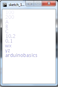
We are going to import a few different numbers/letters and store them in an array. We will then iterate through the array to display the values within.
So let us now create the text file. Copy and paste the following text into notepad and save the file, but remember where you save it, because we will need to know location and the name of the file in order to read from in.

NotepadIconCopy and Paste into Notepad:
100,200,A,B,C,10.2,0.1,wx,yz,arduinobasics


Save the file
I am going to call my file data.txt, and will be saving it to my D drive, so the file will be located here:
  • D:/data.txt

We will now create the processing sketch to read the text file and display the data on the screen.
We will use the comma delimiters to separate the data so that it displays in the following way:


Processing icon The Processing Sketch
 1
2
3
4
5
6
7
8
9
10
11
12
13
14
15
16
17
18
19
20
21
22
23
24
25
26
27
28
29
30
31
32
33
34
35
36
37
38
39
40
/* =============================================================
ReadTextFile and Display on Screen:
Written by ScottC on 15th April 2013 using
Processing version 2.0b8

Website: http://arduinobasics.blogspot.com/
Projects: http://arduinobasics.blogspot.com/p/arduino-basics-projects-page.html

References:
Displaying Text: http://processing.org/reference/text_.html
Reading Text File: http://processing.org/reference/loadStrings_.html
=================================================================*/

void setup(){
size(180,250);
background(255);

/* Read the text file */
String[] lines = loadStrings("D:/data.txt");
int numOfLines=lines.length;
for(int i=0;i<numOfLines;i++){

/* Split the data based on a "," delimiter. */
String[] data = splitTokens(lines[i], ",");
int dataCount = data.length;

for(int j=0; j<dataCount; j++){
/* Set the size and colour of the text */
textSize(16);
fill(100,100,255,50+(j*20));

/* Display the text on the screen */
text(data[j],10,16+(16*j));
}
}
}


void draw(){
}

The code above has the ability to display data from multiple lines within the text file, however for simplicity, I have chosen to use a single line. If I wanted to display more than one line, I would have to change the "for-loops".


Stage Eleven: Read Text File and send to Arduino

In stage 10 we used the Processing  programming language to import a line of data from a text file, break-up the line into pieces (based on comma delimiters) and then displayed the data on the Computer Screen. We will now use this knowledge and take it one step further. We will create a text file, import the data using processing, but this time we will send the data to the Arduino. Meanwhile the Arduino will be waiting patiently for this data, and once it receives the data, it will react according to our needs. We are going to keep this simple. The goal is to send two different letters from the Computer to the Arduino. One letter will turn an LED on, and the other letter will turn the LED off. We will also send an integer to tell the Arduino how long to keep the LED on or off.

GOAL:  Turn an LED on and off by reading a text file.
Our first step in this process is to create a text file that will store our important data. We will store two variables in this file. The first variable will be used to tell the Arduino whether we want to turn the LED on or whether we want to turn the LED off. We will use the letter "O" to turn the LED on, and use the letter "X" to turn the LED off.
The second variable will be a time based variable. It will be used to tell the Arduino "how long" to keep the LED on or off. We will store this variable as an integer and will represent time in "milliseconds".
  • 1000 milliseconds = 1 second
It makes sense to keep these two variables as a pair, however we will separate them using a comma delimitter. We will separate each command by putting the variables on a new line. Copy and paste the following data into notepad (or equivalent text editor), and save the file to your harddrive. I have saved this file as

  • D:/LEDdata.txt

NotepadIconText File Data:Here is the data to put into your text file (notepad):
X,50
O,45
X,40
O,35
X,30
O,25
X,20
O,15
X,10
O,5
X,10
O,15
X,20
O,25
X,30
O,35
X,40
O,45
X,50
O,55
X,60
O,65
X,70
O,75
X,80
O,85
X,90
O,95
X,100
O,200
X,200
O,200
X,500
O,500
X,500
O,500
X,20
O,20
X,20
O,20
X,20
O,20
X,20
O,20
X,20
O,20
X,200
O,20
X,20
O,20
X,20
O,20
X,20
O,20
X,20
O,20
X,20
O,20
X,200
O,20
X,20
O,20
X,20
O,20
X,20
O,20
X,20
O,20
X,200
O,20
X,20
O,20
X,20
O,20
X,20
O,20
X,20
O,20
X,20
O,20
X,20
O,20
X,20


We will now set up the Arduino to accept data from the Computer and react to the Letters
  • "O" to turn the LED on
  • "X" to turn the LED off
  • "E" will be used to test for a successful Serial connection.
We will also get the Arduino to interpret the second variable which will be used to set the amount of time to keep the LED on or off.


Arduino LogoArduino Code:
 1
2
3
4
5
6
7
8
9
10
11
12
13
14
15
16
17
18
19
20
21
22
23
24
25
26
27
28
29
30
31
32
33
34
35
36
37
38
39
40
41
42
43
44
45
46
47
48
49
50
51
52
53
/* Read TextFile Data: Written by ScottC on 24 April 2013
Arduino IDE version: 1.0.4
http://arduinobasics.blogspot.com.au/2013/04/serial-communication-tutorial-part-3.html
*/

/* Global Variables */
byte byteRead; //Used to receive data from computer.
int timeDelay; //time that the LED is On or Off
int maxtimeDelay=10000; //Maximum time delay = 10 seconds
int ledPin=13; //LED connected to pin 13 on Arduino UNO.

void setup() {
//Set pin 13 (ledPin) as an output
pinMode(ledPin, OUTPUT);
// Turn the Serial Protocol ON
Serial.begin(9600);
}

void loop() {
/* check if data has been sent from the computer: */
if (Serial.available()) {
/* read the most recent byte */
byteRead = Serial.read();

switch (byteRead) {
case 69: //This is an enquiry, send an acknowledgement
Serial.println("A");
break;
case 79: //This is an "O" to turn the LED on
digitalWrite(ledPin, HIGH);
break;
case 88: //This is an "X" to turn the LED off
digitalWrite(ledPin, LOW);
break;
case 46: //End of line
//Make sure time delay does not exceed maximum.
if(timeDelay > maxtimeDelay){
timeDelay=maxtimeDelay;
}
//Set the time for LED to be ON or OFF
delay(timeDelay);
Serial.println("S");
timeDelay=0; //Reset timeDelay;
break;
default:
//listen for numbers between 0-9
if(byteRead>47 && byteRead<58){
//number found, use this to construct the time delay.
timeDelay=(timeDelay*10)+(byteRead-48);
}
}
}
}

Our next step is to import the data in the text file into Processing and then send the data to the Arduino. You may want to review Stage 10 of this tutorial for another example of importing text file data into Processing. You may also want to review stage 7 which shows how to receive data from an Arduino.
We will import all of the data from the file when we push a button on the Processing Window, and send this data to the Arduino via the USB cable that is connected to the computer. We are going to use the same COM port that the Computer uses to upload Arduino Sketches, therefore it is important that you close the Arduino Serial Monitor before you run the processing sketch, otherwise you will get an error which states that the COM port is not available.


Processing iconProcessing Code:
 1
2
3
4
5
6
7
8
9
10
11
12
13
14
15
16
17
18
19
20
21
22
23
24
25
26
27
28
29
30
31
32
33
34
35
36
37
38
39
40
41
42
43
44
45
46
47
48
49
50
51
52
53
54
55
56
57
58
59
60
61
62
63
64
65
66
67
68
69
70
71
72
73
74
75
76
77
78
/* TextFile Data sender (Stage 11) 
Written by ScottC on 24th April 2013
using Processing Version 2.0b8

The full tutorial can be found here:
http://arduinobasics.blogspot.com/2013/04/serial-communication-tutorial-part-3.html
*/

import processing.serial.*;

Serial comPort; //The com port used between the computer and Arduino
int counter=0; // Helps to keep track of values sent.
int numItems=0; //Keep track of the number of values in text file
String comPortString; //String received From Arduino
String textFileLines[]; //Array of text file lines
String lineItems[]; //Array of line items

void setup(){
comPort = new Serial(this, Serial.list()[0], 9600); //Setup the COM port
comPort.bufferUntil('\n'); //Generate a SerialEvent when a newline is received
background(255,0,0); //Start with a Red background
}

/* Draw method is not used in this sketch */
void draw(){
}

//When the mouse is pressed, write an "E" to COM port.
//The Arduino should send back an "A" in return. This will
//generate a serialEvent - see below.
void mousePressed() {
comPort.write("E");
}

void serialEvent(Serial cPort){
comPortString = cPort.readStringUntil('\n');
if(comPortString != null) {
comPortString=trim(comPortString);

/*If the String received = A, then import the text file
change the background to Green, and start by sending the
first line of the text file to the Arduino */
if(comPortString.equals("A")){
textFileLines=loadStrings("D:/LEDdata.txt");
background(0,255,0);
sendLineNum(counter);
}

/*If the the String received = S, then increment the counter
which will allow us to send the next line in the text file.
If we have reached the end of the file, then reset the counter
and change the background colour back to red. */
if(comPortString.equals("S")){
counter++;
if(counter > (textFileLines.length-1)){
background(255,0,0);
counter=0;
} else {
sendLineNum(counter);
}
}
}
}


/*The sendLineNum method is used to send a specific line
from the imported text file to the Arduino. The first
line item tells the Arduino to either switch the LED on or off.
The second line item, tells the Arduino how long to keep the
LED on or off. The full-stop is sent to the Arduino to indicate
the end of the line. */

void sendLineNum(int lineNumber){
lineItems=splitTokens(textFileLines[lineNumber],",");
comPort.write(lineItems[0]);
comPort.write(lineItems[1]);
comPort.write(".");
}


Stage Twelve: To be continued..


I need to finish my XBee tutorial before doing this stage. But am just about to start studying again. So this stage probably won't get completed for another couple of months. But I hope there is enough content to keep you satisfied for the time being.


Description: Serial Communication Tutorial (Part 3) Rating: 3.5 Reviewer: Unknown ItemReviewed: Serial Communication Tutorial (Part 3)
Arduino UNO - XBee Setup Reviewed by Unknown on 18:15 Rating: 4.5

Arduino UNO - XBee Setup

There are many XBee tutorials out there, but I could not find one that I could apply to my specific Arduino/Shield/Xbee configuration. While this particular configuration may not apply to you, perhaps it will send you in the right direction, so please read on.
Please note, that your XBee shield may require you to perform extra steps, so please do further reading before jumping in head first. I am not an expert, so don't blame me if you fry your board.

The following set of steps worked for me:


Step 1: Download and Install X-CTU

The easiest way to setup your XBee module is via the X-CTU software from Digi. It can be downloaded from their site here:  http://www.digi.com/support/productdetail?pid=3257

  • Select  the Diagnostics, Utilities and MIBs section


  • Download and install the XCTU 32-bit ver 5.2.7.5 installer (do a virus check after download)
  • Please note that this is for Windows platforms only !

  • FYI: We will run the software later


Step 2: Upload the bare-minimum script on your Arduino controller

I perform this step to prevent any previous projects from interfering. This may not be necessary, but I tend to do this before wiring up any of my new projects. This is the script I load onto the Arduino:

Bare Minimum Arduino Sketch:
1
2
3
4
5
6
7
void setup() {

}

void loop() {

}


Step 3: Connect the Shield to Arduino, and XBee to Shield.


  • Disconnect the Arduino UNO from the computer. 

  • Insert the XBee module into the Shield.
  • This is the XBee Shield and XBee module side by side


    This is the XBee module on the XBee Shield


  • The pins from the XBee module should slot into the respective headers on the Shield.


  • Connect the XBee shield to the Arduino

  • The pins from the XBee shield should slot into the respective headers on the Arduino board.


  • Move the little white switch in the corner to USB.

    • There are 2 options - USB mode and XBee mode.
    • We want USB mode which will allow the computer to communicate with the XBee module


Step 4: Connect Arduino to computer, and run the X-CTU Software


  • With the XBee module and Shield connected to the Arduino, and the Shield's white switch in USB mode;  connect the Arduino to the computer using a USB cable.
  • This Arduino board appears as COM7 on my computer.
  • Here is what the X-CTU software looks like when it loads up


  • Press the Test / Query button to see if the computer can talk to the XBee module.
    • If successful, you should see something like this:


  • If you accidentally leave the XBee shield in XBee mode, or if your computer fails to communicate with the XBee module, you may encounter these screens.


If you get a successful Test / Query, then move onto the next step.


Step 5: Read XBee Firmware settings:

We can now try to read the XBee firmware settings by
  • Selecting the Modem Configuration Tab

  • Select the Read button to read the XBee firmware settings


Step 6: Download older version of firmware if necessary

  • If you did not have any issues with the previous step, then continue to step 7, otherwise read on.
  • In my case, the software could not find the firmware file necessary to read the firmware settings.
  • In step 4, I could see that I had the XB24 Modem type, and 10E8 firmware version,

  • I tried downloading new versions, but this did not seem to work, as the computer could not detect any newer updates available. The problem I had, was that I needed an "older version" of firmware to communicate with the XBee module in order to read/write new settings to it.
  • I could not select the firmware version from the drop down boxes, which indicated that this particular firmware version was not installed on my computer. So here is what I did.
    • I went back to the Digi site and selected the Firmware update section.
    • This provided a link to an FTP site with "previous versions" of firmware.


  • I then selected the relevant firmware version from the list, and downloaded the zip file to a logical folder on my hard-drive.  There is no need to unzip the file, because the X-CTU software will look for a zipped file.


  • In the X-CTU software, in the Modem Configurations tab, select the "Download new versions button", and select File. Navigate to the zip-file just downloaded and select it. 


  • The software should tell you that it has updated successfully or something to that effect.
  • The modem type and version should now be an available option in the drop down boxes, however, we will continue where we left off (in step 5) and try an read the firmware settings from the XBee module, by pressing the Read button in the Modem Configurations tab on the X-CTU software.
  • It should look something like this:

TO BE CONTINUED.......
Description: Arduino UNO - XBee Setup Rating: 3.5 Reviewer: Unknown ItemReviewed: Arduino UNO - XBee Setup
Back to top