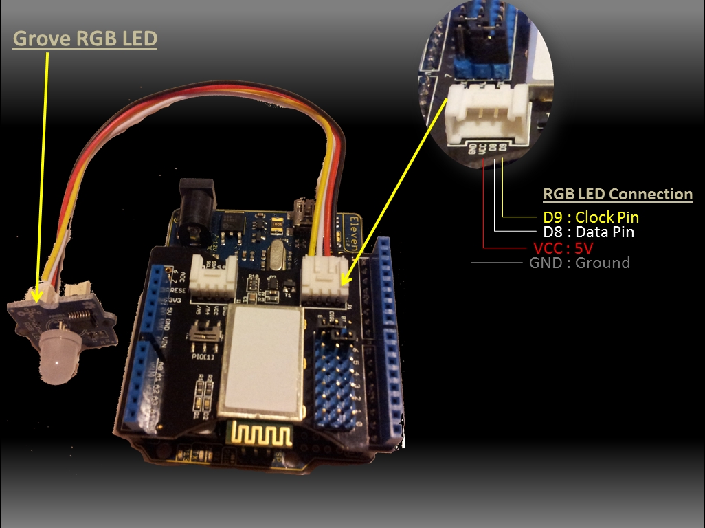
The bluetooth shield used in this project is a great way to detach the Arduino from your computer. What is even better, is that the shield allows you to control your arduino from your mobile phone or other bluetooth enabled device through simple Serial commands. In this tutorial we will connect a Grove Chainable RGB LED to the bluetooth shield directly, and send simple commands using the Bluetooth SPP app on a Samsung Galaxy S2 to change the colour of the LED (Red , Green and Blue)
/* This project combines the code from a few different sources. This project was put together by ScottC on the 15/01/2013 http://arduinobasics.blogspot.com/
Bluetooth slave code by Steve Chang - downloaded from : http://www.seeedstudio.com/wiki/index.php?title=Bluetooth_Shield
Grove Chainable RGB code can be found here : http://www.seeedstudio.com/wiki/Grove_-_Chainable_RGB_LED#Introduction
*/
#include <SoftwareSerial.h> //Software Serial Port
#define uint8 unsigned char #define uint16 unsigned int #define uint32 unsigned long int
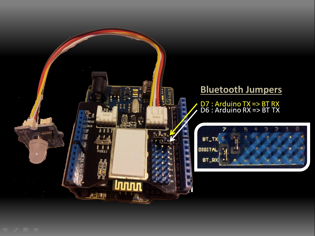
#define RxD 6 // This is the pin that the Bluetooth (BT_TX) will transmit to the Arduino (RxD) #define TxD 7 // This is the pin that the Bluetooth (BT_RX) will receive from the Arduino (TxD)
#define DEBUG_ENABLED 1
int Clkpin = 9; //RGB LED Clock Pin (Digital 9) int Datapin = 8; //RGB LED Data Pin (Digital 8)
SoftwareSerial blueToothSerial(RxD,TxD);
/*----------------------SETUP----------------------------*/ void setup() { Serial.begin(9600); // Allow Serial communication via USB cable to computer (if required) pinMode(RxD, INPUT); // Setup the Arduino to receive INPUT from the bluetooth shield on Digital Pin 6 pinMode(TxD, OUTPUT); // Setup the Arduino to send data (OUTPUT) to the bluetooth shield on Digital Pin 7 pinMode(13,OUTPUT); // Use onboard LED if required. setupBlueToothConnection(); //Used to initialise the Bluetooth shield
pinMode(Datapin, OUTPUT); // Setup the RGB LED Data Pin pinMode(Clkpin, OUTPUT); // Setup the RGB LED Clock pin
}
/*----------------------LOOP----------------------------*/ void loop() { digitalWrite(13,LOW); //Turn off the onboard Arduino LED char recvChar; while(1){ if(blueToothSerial.available()){//check if there's any data sent from the remote bluetooth shield recvChar = blueToothSerial.read(); Serial.print(recvChar); // Print the character received to the Serial Monitor (if required)
//If the character received = 'r' , then change the RGB led to display a RED colour if(recvChar=='r'){ Send32Zero(); // begin DataDealWithAndSend(255, 0, 0); // first node data Send32Zero(); // send to update data }
//If the character received = 'g' , then change the RGB led to display a GREEN colour if(recvChar=='g'){ Send32Zero(); // begin DataDealWithAndSend(0, 255, 0); // first node data Send32Zero(); // send to update data }
//If the character received = 'b' , then change the RGB led to display a BLUE colour if(recvChar=='b'){ Send32Zero(); // begin DataDealWithAndSend(0, 0, 255); // first node data Send32Zero(); // send to update data } }
//You can use the following code to deal with any information coming from the Computer (serial monitor) if(Serial.available()){ recvChar = Serial.read();
//This will send value obtained (recvChar) to the phone. The value will be displayed on the phone. blueToothSerial.print(recvChar); } } }
//The following code is necessary to setup the bluetooth shield ------copy and paste---------------- void setupBlueToothConnection() { blueToothSerial.begin(38400); //Set BluetoothBee BaudRate to default baud rate 38400 blueToothSerial.print("\r\n+STWMOD=0\r\n"); //set the bluetooth work in slave mode blueToothSerial.print("\r\n+STNA=SeeedBTSlave\r\n"); //set the bluetooth name as "SeeedBTSlave" blueToothSerial.print("\r\n+STOAUT=1\r\n"); // Permit Paired device to connect me blueToothSerial.print("\r\n+STAUTO=0\r\n"); // Auto-connection should be forbidden here delay(2000); // This delay is required. blueToothSerial.print("\r\n+INQ=1\r\n"); //make the slave bluetooth inquirable Serial.println("The slave bluetooth is inquirable!"); delay(2000); // This delay is required. blueToothSerial.flush(); }
//The following code snippets are used update the colour of the RGB LED-----copy and paste------------ void ClkProduce(void){ digitalWrite(Clkpin, LOW); delayMicroseconds(20); digitalWrite(Clkpin, HIGH); delayMicroseconds(20); }
You don't need to download a library to get this project running. But if you plan to use bluetooth shields to get 2 Arduinos to communicate to each other, then I would advise that you download the library files (which are just examples) from the Seeedstudio site : here.
Visit this site to setup your phone or laptop for bluetooth communication to the shield - here
The app used on my Samsung Galaxy S2 phone was "Bluetooth SPP"
You will initially need to enter a pin of '0000' to establish a connection to the Bluetooth shield - which will appear as "SeeedBTSlave" or whatever text you place on line 90 of the Arduino code above.
Warning !
Not all phones are compatible with the bluetooth shield. If you have used this shield before - please let me know what phone you used - so that we can build a list and inform others whether their phone is likely to work with this project or not. Obviously - those phones that do not have bluetooth within - will not work :). And I have not tried any other apps either
I got it to work very easily with my Samsung Galaxy S2 using the free Bluetooth SPP app from the google play store.
This was fun, but I want to make my own app ! Have a look at my latest 4-part tutorial which takes you step-by-step through the process of building your own app using the Processing/Android IDE. You can build your own GUI interface on your Android Phone and get it to communicate via Bluetooth to your Arduino/Bluetooth Shield. Click on the links below for more information:
This project utilises the HC-SR04 ultrasonic sensor to scan for nearby objects. You can program the Arduino to sound an alarm when the sensor detects an object within a specific vicinity. Connecting it to a computer allows data to be plotted to make a simple sonar scanner. The scanning ability is made possible through the use of a hobby servo motor SG-5010, and an Adafruit motor shield v1.0. This project could easily be extended to provide object avoidance for any robotics project. This tutorial was designed so that you could see how the components interact, and also to see how you can use and expand the functionality of the motor shield.
Gauge parts: Paper (to print the face of the gauge), and some glue to stick it to the wood. MDF Standard panel (3mm width) - for the top and base of the gauge, and the pointer. Galvanized bracket (25x25x40mm) Timber screws: Hinge-long threads csk head Phillips drive (4G x 12mm) Velcro dots - to allow temporary application of the mini-breadboard to the gauge.
The gauge was used as a customisable housing for the Arduino and related parts, and to provide some visual feedback of the servo position.
Part of the sketch above was created using Fritzing.
The Servo motor can be connected to either of the Servo motor pins (Digital 9 or 10). In this case, the Servo is attached to digital pin 10.Make sure you read the servo motor data sheet and identify the VCC (5V), GND, and Signal connectors. Not all servos have the same colour wires. My servo motor has a white signal wire, a red VCC wire and a black GND wire.
Also when connecting your wires to the HC-SR04, pay attention to the front of the sensor. It will identify the pins for you. Make sure you have the sensor facing the correct way. In this sketch, the sensor is actually facing towards you.
In this sketch - we connect the Echo pin to Analog pin 0 (A0). Trigger pin to Analog pin 1 (A1) VCC to a 5V line/pin and GND to a GND line/pin
Pay attention to your motor shield, I have seen some pictures on the internet where the 5V and GND are reversed.
Arduino Code: You can download the Arduino IDE from this site.
/* ArduinoBasics: Sonar Project - Created by Scott C on 10 Jan 2013 http://arduinobasics.blogspot.com/2013/01/arduino-basics-sonar-project-tutorial.html This project uses the Adafruit Motor shield library (copyright Adafruit Industries LLC, 2009 this code is public domain, enjoy!) The HC-SR04 sensor uses some code from the following sources: From Virtualmix: http://goo.gl/kJ8Gl Modified by Winkle ink here: http://winkleink.blogspot.com.au/2012/05/arduino-hc-sr04-ultrasonic-distance.html And modified further by ScottC here: http://arduinobasics.blogspot.com/ on 10 Nov 2012. */
#include <AFMotor.h> #include <Servo.h>
// DC hobby servo Servo servo1;
/* The servo minimum and maximum angle rotation */ staticconstint minAngle = 0; staticconstint maxAngle = 176; int servoAngle; int servoPos; int servoPin = 10;
/* Define pins for HC-SR04 ultrasonic sensor */ #define echoPin A0 // Echo Pin = Analog Pin 0 #define trigPin A1 // Trigger Pin = Analog Pin 1 #define LEDPin 13 // Onboard LED long duration; // Duration used to calculate distance long HR_dist=0; // Calculated Distance int HR_angle=0; // The angle in which the servo/sensor is pointing int HR_dir=1; // Used to change the direction of the servo/sensor int minimumRange=5; //Minimum Sonar range int maximumRange=200; //Maximum Sonar Range
/*--------------------SETUP()------------------------*/ void setup() { //Begin Serial communication using a 9600 baud rate Serial.begin (9600);
// Tell the arduino that the servo is attached to Digital pin 10. servo1.attach(servoPin);
//Setup the trigger and Echo pins of the HC-SR04 sensor pinMode(trigPin, OUTPUT); pinMode(echoPin, INPUT); pinMode(LEDPin, OUTPUT); // Use LED indicator (if required) }
/* check if data has been sent from the computer: */ if (Serial.available()) {
/* This expects an integer from the Serial buffer */ HR_angle = Serial.parseInt();
/* If the angle provided is 0 or greater, then move servo to that position/angle and then get a reading from the ultrasonic sensor */ if(HR_angle>-1){ /*Make sure that the angle provided does not go beyond the capabilities of the Servo. This can also be used to calibrate the servo angle */ servoPos = constrain(map(HR_angle, 0,180,minAngle,maxAngle),minAngle,maxAngle); servo1.write(servoPos);
/* Call the getDistance function to take a reading from the Ultrasonic sensor */ getDistance(); } } }
/*--------------------getDistance() FUNCTION ---------------*/ void getDistance(){
/* The following trigPin/echoPin cycle is used to determine the distance of the nearest object by bouncing soundwaves off of it. */ digitalWrite(trigPin, LOW); delayMicroseconds(2);
//Calculate the distance (in cm) based on the speed of sound. HR_dist = duration/58.2;
/*Send the reading from the ultrasonic sensor to the computer */ if (HR_dist >= maximumRange || HR_dist <= minimumRange){ /* Send a 0 to computer and Turn LED ON to indicate "out of range" */ Serial.println("0"); digitalWrite(LEDPin, HIGH); } else { /* Send the distance to the computer using Serial protocol, and turn LED OFF to indicate successful reading. */ Serial.println(HR_dist); digitalWrite(LEDPin, LOW); } }
Servo Angles: You will notice on line 22, the maximum servo angle used was 176. This value was obtained through trial and error (see below).
Calibrating the servo angles You may need to calibrate your servo in order to move through an angle of 0 to 180 degrees without straining the motor. Go to line 21-22 and change the minAngle to 0 and the maxAngle to 180. Once you load the sketch to the Arduino/Freetronics ELEVEN, you can then open the Serial Monitor and type a value like 10 <enter>, and then keep reducing it until you get to 0. If you hear the servo motor straining, then move it back up to a safe value and change the minimum servo angle to that value. Do the same for the maximum value.
In this example, the servo's minAngle value was 0, and maxAngle value was 176 after calibration, however, as you can see from the video, the physical range of the servo turned out to be 0 to 180 degrees.
The Processing Sketch You can download the Processing IDE from this site.
/* Created by ScottC on 10 Jan 2013 http://arduinobasics.blogspot.com/2013/01/arduino-basics-sonar-project-tutorial.html */
import processing.serial.*;
int distance; int angle=0; int direction=1;
int[] alphaVal = newint[100]; // used to fade the lines int[] distance2 = newint[100]; // used to store the line lengths int lineSize = 4; // line length multiplier (makes it longer)
String comPortString; Serial comPort;
/*---------------------SETUP---------------------------*/ void setup( ) { size(displayWidth,displayHeight); //allows fullscreen view smooth(); background(0); // set the background to black
/*Open the serial port for communication with the Arduino Make sure the COM port is correct - I am using COM port 8 */ comPort = new Serial(this, "COM8", 9600); comPort.bufferUntil('\n'); // Trigger a SerialEvent on new line
/*Initialise the line alphaValues to 0 (ie not visible) */ for(int i=0; i<91; i++){ alphaVal[i] = 0; } }
/*---------------------DRAW-----------------*/ void draw( ) { background(0); //clear the screen
/*Draw each line and dot */ for(int i=0; i<91; i++){
/*Gradually fade each line */ alphaVal[i]=alphaVal[i]-4;
/*Once it gets to 0, keep it there */ if(alphaVal[i]<0){ alphaVal[i]=0; }
/*The colour of the line will change depending on the distance */ stroke(255,distance2[i],0,alphaVal[i]);
/* Use a line thickness of 2 (strokeweight) to draw the line that fans out from the bottom center of the screen. */ strokeWeight(2); line(width/2, height, (width/2)-cos(radians(i*2))*(distance2[i]*lineSize), height-sin(radians(i*2))*(distance2[i]*lineSize));
/* Draw the white dot at the end of the line which does not fade */ stroke(255); strokeWeight(1); ellipse((width/2)-cos(radians(i*2))*(distance2[i]*lineSize), height-sin(radians(i*2))*(distance2[i]*lineSize),5,5); } }
/* A mouse press starts the scan. There is no stop button */ void mousePressed(){ sendAngle(); }
/*When the computer receives a value from the Arduino, it will update the line positions */ void serialEvent(Serial cPort){ comPortString = cPort.readStringUntil('\n'); if(comPortString != null) { comPortString=trim(comPortString);
/* Use the distance received by the Arduino to modify the lines */ distance = int(map(Integer.parseInt(comPortString),1,200,1,height)); drawSonar(angle,distance);
/* Send the next angle to be measured by the Arduino */ sendAngle(); } }
/*---------------------------sendAngle() FUNCTION----------------*/ void sendAngle(){ //Send the angle to the Arduino. The fullstop at the end is necessary. comPort.write(angle+".");
/*Increment the angle for the next time round. Making sure that the angle sent does not exceed the servo limits. The "direction" variable allows the servo to have a sweeping action.*/ angle=angle+(2*direction); if(angle>178||angle<1){ direction=direction*-1; } }
/*-----------------sketchFullScreen(): Allows for FullScreen view------*/ boolean sketchFullScreen() { returntrue; }
/*----------------- drawSonar(): update the line/dot positions---------*/ void drawSonar(int sonAngle, int newDist){ alphaVal[sonAngle/2] = 180; distance2[sonAngle/2] = newDist; }
The IRTEMP module from Freetronics is an infrared remote temperature sensor that can be incorporated into your Arduino / microcontroller projects. It can scan a temperature between -33 to +220 C, and can be operated using a 3.3 to 5V power supply. It can be powered directly from the Arduino 5V pin. This module can also provide an ambient temperature reading if required. The Servo used in this project is a SG-5010 standard servo which will be utilised to display the temperature reading from the IRTEMP module.
Gauge parts: Paper (to print the face of the gauge), and some glue to stick it to the wood. MDF Standard panel (3mm width) - for the top and base of the gauge. Galvanized bracket (25x25x40mm) Timber screws: Hinge-long threads csk head Phillips drive (4G x 12mm)
/* ------------------------------------------------------- Analog IR Temperature Gauge: written by ScottC on 1st Dec 2012. http://arduinobasics.blogspot.com/2012/12/arduino-basics-analog-ir-temperature.html
* Some of the code was adapted from a sketch by Andy Gelme (@geekscape) * For more information on using the IRTEMP see www.freetronics.com/irtemp * IRTemp library uses an Arduino interrupt: * If PIN_CLOCK = 2, then Arduino interrupt 0 is used * If PIN_CLOCK = 3, then Arduino interrupt 1 is used ---------------------------------------------------------*/
#include "IRTemp.h" #include <Servo.h>
Servo servo1; staticconstbyte PIN_DATA = 2; staticconstbyte PIN_CLOCK = 3; // Must be either pin 2 or pin 3 staticconstbyte PIN_ACQUIRE = 4;
/* If you want the ambient temperature instead - then use the code below. */ //float ambientTemperature = irTemp.getAmbientTemperature(SCALE); //printTemperature("Ambient", ambientTemperature);
Ambient temperature: If you want to get the ambient temperature from the IRTEMP module, then have a look at lines 58-59. Servo Angles: You will notice on line 36, the maximum servo angle used was 175. This value was obtained through trial and error (see below).
Calibrating the servo angles You may need to calibrate your servo in order to move through an angle of 0 to 180 degrees without straining the motor.Change the minAngle on line 35to a safe value (for example: 10), and the maxAngle on line 36 to a value like 170. Remove the comment tag (//) on line 76, and then run the sketch. Lower the minAngle until it reaches the minimum value on the gauge, making sure that the servo doesn't sound like it is straining to keep it in position.
Add the comment tag (//) back in, and then take out the comment tag for line 79. And follow a similar process, until you reach the maximum value on the gauge. Once again, make sure that the servo is not making a straining noise to hold it at that value. Make sure to add the comment tag back in, when you have finished the calibration.
In this example, the servo's minAngle value was 0, and maxAngle value was 175 after calibration, however, as you can see from the video, the physical range of the servo turned out to be 0 to 180 degrees.
The Temperature Gauge Picture
The following gauge was created in Microsoft Excel using an X-Y chart. Data labels were manually repositioned in order to get the desired numerical effect.
Description: Analog IR Temperature gauge
Rating: 3.5
Reviewer: Unknown
ItemReviewed: Analog IR Temperature gauge