.
E-Paper Barcode 39 Reviewed by Unknown on 01:27 Rating: 4.5

E-Paper Barcode 39

E-Paper (or Electronic paper) is a display technology that mimics the appearance of ordinary ink on paper. E-paper displays do not emit light, rather they reflect light, thus making them much more comfortable to read and provide a wider viewing angle than most light emitting displays (source: Wikipedia).

I printed something to an E-paper display, unplugged it, and could still read the message clearly months later. These E-paper displays are great for showing information that is static for long periods. You only need to provide power when the data or information needs updating.

Barcodes are used everywhere, and one of the simplest Barcodes to generate is the Code 39 format (also known as Code 3 of 9). I used an E-paper shield and E-paper module to display a number in this barcode format. I then tested it with a Barcode reader and it worked perfectly.
This tutorial will show you how to send a number to the Arduino from the Serial Monitor, and display the Barcode on the E-paper module.

Note: If you are using an Arduino UNO (or compatible), you will also need to get a micro SDHC card.


The Video


The video will show you how to assemble the shield and the module onto the Arduino, and also how to install the SDHC card.


Parts Required:

Library Download


To use the e-paper shield, you will need to download the Small e-paper Shield library.
This library will allow you to use the following functions on the e-paper shield:
  • begin : to set up the size of the e-paper panel
  • setDirection : to set up the display direction
  • drawChar : to display a Character at a specified position
  • drawString : to display a String of characters at a specified position
  • drawNumber and drawFloat : to display a number
  • drawLine : to draw a line
  • drawHorizontalLine : to draw a horizontal line
  • drawVerticalLine : to draw a vertical line
  • drawCircle : to draw a circle
  • fillCircle : to draw and fill a circle
  • drawRectangle : to draw a rectangle
  • fillRectangle : to draw and fill a rectangle
  • drawTriangle : to draw a triangle
You can also draw an image to the e-paper shield.

For more information on how to use these functions, please visit the seeedstudio wiki. If you are unfamiliar with installing libraries - then have a look at the following sites:

Barcode 39 Info

Barcode 39 (or Code 3 of 9) is a barcode that consists of black and white vertical lines. These lines can be thick or thin. Each character can be coded using 9 alternating black and white bars. The barcode always starts with a black bar, and ends with a black bar.

If you code using thin lines only, then each character can be coded using a total of 12 bars. A wide black line is essentially two thin black lines next to each other. Same goes for a wide white line. Because there are now only 2 options (black or white), you can create a binary code. I used a 1 for black bars, and 0 for white bars. If there was a thick black bar, then this would be represented with a 11. A thick white bar would be 00.

Each barcode sequence starts and ends with a hidden * character. Therefore if you were to display just the number 1, you would have to provide the code for *1*.

  • * = 100101101101
  • 1 = 110100101011
  • * = 100101101101
Notice that each character starts with a 1 and ends with a 1.
Something also to take note of: is that each character is separated by a thin white line (and not represented in the binary code).

All of these 0's and 1's can get a bit confusing, so I decided to represent these binary numbers as decimals. For example, the picture below shows how a 0 and an 8 would be coded (without the *):


The table below provides the binary and decimal codes for each number used in this tutorial. I have also included for your own reference, each letter of the alphabet, however I did not use these in this tutorial.

The binary representation of each character in this table was obtained from this site.
www.barcodeisland.com is a great resource of information about barcodes.

I adapted their binary code into a decimal equivalent, and therefore had to create my own table.


Arduino Sketch


  1
2
3
4
5
6
7
8
9
10
11
12
13
14
15
16
17
18
19
20
21
22
23
24
25
26
27
28
29
30
31
32
33
34
35
36
37
38
39
40
41
42
43
44
45
46
47
48
49
50
51
52
53
54
55
56
57
58
59
60
61
62
63
64
65
66
67
68
69
70
71
72
73
74
75
76
77
78
79
80
81
82
83
84
85
86
87
88
89
90
91
92
93
94
95
96
97
98
99
100
101
102
103
104
105
106
107
108
109
110
111
112
113


/* ===============================================================
      Project: Display Barcodes on an e-Paper Panel
       Author: Scott C
      Created: 6th January 2015
  Arduino IDE: 1.0.5
      Website: http://arduinobasics.blogspot.com/p/arduino-basics-projects-page.html
  Description: This project will allow you to send a number from the Serial 
               Monitor to the Arduino. The number will then be displayed on 
               the e-Paper panel as a Code-39 barcode (and text).
================================================================== */

#include <ePaper.h>
#include <SPI.h>
#include <SD.h>
#include "GT20L16_drive.h"

const int maxBarcodeSize = 10; // set the maximum barcode size to 10 digits
int barcode[maxBarcodeSize]; // initialise the barcode array to the maximum 10 digits
int barcodeText[maxBarcodeSize]; // initialise the barcodeText array to the maximum 10 digits
int barcodePos; // Used to identify each digit within the barcode
int barcodeLength; // Used to identify the actual length of the barcode

/*  The following array holds the decimal code for each digit (0-9). 
    Each digit can be converted to binary and then drawn as a barcode.
                         0     1     2     3     4     5     6     7     8     9         */
int barcodeDecimal[] = {2669, 3371, 2859, 3477, 2667, 3381, 2869, 2651, 3373, 2861};

int astrix = 2413; // "*" character decimal code used at beginning and end of barcode sequence


/*  When drawBarcode = "no", the program will not draw the barcode on the e-paper panel
    When drawBarcode = "yes", the command to draw the barcode on the e-paper panel will be triggered. */
String drawBarcode = "no";


/*  This variable is the x Position on the e-Paper panel screen */
int xPosition;


void setup(){
    Serial.begin(9600); // Initialise Serial communication
    EPAPER.begin(EPD_2_0); // Set the e-Paper panel size to 2 inches
    EPAPER.setDirection(DIRNORMAL); // Set the e-Paper panel display direction (to Normal)
    eSD.begin(EPD_2_0); // Prepares the SD card
    GT20L16.begin(); // Initialise the GT20L16 font chip on the e-Paper panel
    barcodePos = 0;                    // Set the barcode digit to the first digit in the barcode
    EPAPER.clear_sd(); // Clear the screen when starting sketch
    
    EPAPER.drawString("http://arduinobasics", 10, 20); //splash screen text
    EPAPER.drawString(".blogspot.com", 60, 40);
    
    EPAPER.display(); // Display the splash screen
}


void loop(){
  
    // The Arduino will wait until it receives data from the Serial COM port
    
    while (Serial.available()>0){
      barcodeText[barcodePos] = Serial.read();
        
      if(barcodeText[barcodePos]>47 && barcodeText[barcodePos]<58){ // A number was sent
         barcode[barcodePos] = barcodeText[barcodePos]-48;            // Convert the decimal value from the serial monitor to a Number
      } 
      
      if(barcodeText[barcodePos]==46){ // If a "." is detected, then barcode is complete
        barcodeLength = barcodePos;                   // Set the length of the barcode (used later)
        drawBarcode = "yes"; // We can now draw the barcode
        
      }
      
      if(barcodePos>(maxBarcodeSize-1)){ // Check if maximum barcode length has been reached
       barcodeLength = barcodePos;                    // Set the length of the barcode (used later)
       drawBarcode = "yes"; // We can now draw the barcode
      }
     
       barcodePos++;                                  // Move to the next barcode digit
    }
    
    if(drawBarcode == "yes"){ // Only draw the barcode when drawBarcode = "yes"
      
      EPAPER.clear_sd(); // Clear the e-Paper panel in preparation for barcode
      xPosition = 15;                                 // Set the initial white-space on the left
      drawBCode(astrix, ' '); // Each barcode starts with an invisible *
      
      for(int digit=0; digit<barcodeLength; digit++){ // Start drawing the barcode numbers
        drawBCode(barcodeDecimal[barcode[digit]], barcodeText[digit]);  // Call the drawBCode method (see below)
      }
      
      drawBCode(astrix, ' '); // Each barcode ends with an invisible *
      EPAPER.display(); // Show the barcode image and text
      
      drawBarcode = "no"; // Stop it from drawing again until next barcode sequence sent
      barcodePos=0;                                   // Re-initialise the position back to first digit (in preparation for the next barcode)
    }
}


//The drawBCode method is the key method for drawing the barcode on the e-paper panel
void drawBCode(int bCode, char bCodeText){
  xPosition++;                                        // There is a white space between each digit
  for (int barPos = 11; barPos > -1; barPos--){ // Cycle through the binary code for each digit. Each digit is made up of 11 bars
    xPosition++;                                      // Advance the xPosition to draw the next bar (white or black)
    if(bitRead(bCode, barPos)==1){ // If the binary digit at this position is a 1, then draw a black line
      EPAPER.drawVerticalLine(xPosition, 10, 60); // This draws the individual Bar (black - only)
    }                                                 // If the binary digit is a 0, then it is left blank (or white).
  }
  EPAPER.drawChar(bCodeText, xPosition-9, 75); // Draw the human readable (text) portion of the barcode
}


There is something weird about the E-paper shield library which tends to display the word "temperature:" in the Serial monitor when opened, and with each serial transmission. Don't worry about this. Just ignore it.'


This tutorial shows you how to create your own renewable barcodes. While this only handles numbers at this stage, it could just as easily be upgraded to handle text as well. If you liked this tutorial, please give it a google+ thumbs up, share it with your friends, or just write a comment. Thankyou for visiting my blog.


If you like this page, please do me a favour and show your appreciation :

 
Visit my ArduinoBasics Google + page.
Follow me on Twitter by looking for ScottC @ArduinoBasics.
Have a look at my videos on my YouTube channel.


However, if you do not have a google profile...
Feel free to share this page with your friends in any way you see fit.


Description: E-Paper Barcode 39 Rating: 3.5 Reviewer: Unknown ItemReviewed: E-Paper Barcode 39
Bluetooth Android Processing 4 Reviewed by Unknown on 00:23 Rating: 4.5

Bluetooth Android Processing 4

PART FOUR

The Video


This is part 4 of my tutorial on designing an Android Phone Bluetooth App using the Android/Processing language. The App sends information to an Arduino via Bluetooth after pressing a button on the phone. The RGB LED attached to the Arduino Uno (or compatible board) will change colour depending on the button being pressed on the phone. The Arduino gains Bluetooth capabilities through the Seeedstudio Bluetooth shield (which can be found here).

Parts 1-3 of the tutorial were designed to take you step-by-step through designing the app. If you are wondering what you missed, here is a summary:

This is what you'll find in partone:
  • Downloading and setting up the Android SDK
  • Downloading the Processing IDE
  • Setting up and preparing the Android device
  • Running through a couple of Processing/Android sketches on an Andoid phone.

This is what you will find in part two:

  • Introducing Toasts (display messages)
  • Looking out for BluetoothDevices using BroadcastReceivers
  • Getting useful information from a discovered Bluetooth device
  • Connecting to a Bluetooth Device
  • An Arduino Bluetooth Sketch that can be used in this tutorial

This is what you will find in part three:

  • InputStreams and OutputStreams
  • Error Logs using logcat
  • Testing the InputStreams and OutputStreams
  • Using the APWidgets library to create buttons
  • Adding Buttons to the BlueTooth Project


In Part 4, we simplify and strip down the App so that it will only sends a specific String to the Arduino via Bluetooth. The String sent to the Arduino depends on the Button being pressed. The code has been cleaned up and has many comments to help you understand what is going on. You should be able to run this sketch without having to go back through parts one, two or three of the tutorial. This fourth part of the tutorial was designed for those people who want the final end product, and are happy to work it out for themselves. I hope this serves you well.
I will therefore assume that you have already setup your phone and have downloaded all the neccesary drivers, libraries, SDKs and IDEs. If not, then here are a few quick links:
If you are a bit lost and want want a bit more information then please go through parts one, two and three of this tutorial.
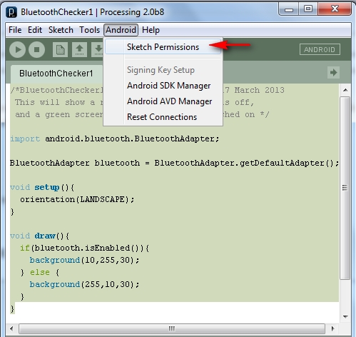
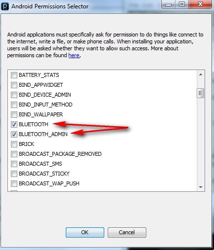
Make sure that you have selected the Bluetooth permissions as per the following:

  • Android > Sketch permissions  (as per the picture below)


Make sure that BLUETOOTH and BLUETOOTH_ADMIN are selected (as per the picture below). Then press the OK button.


Then copy and paste the following sketch into the processing/android IDE:

Android/Processing Sketch 9: Bluetooth App2

 1
2
3
4
5
6
7
8
9
10
11
12
13
14
15
16
17
18
19
20
21
22
23
24
25
26
27
28
29
30
31
32
33
34
35
36
37
38
39
40
41
42
43
44
45
46
47
48
49
50
51
52
53
54
55
56
57
58
59
60
61
62
63
64
65
66
67
68
69
70
71
72
73
74
75
76
77
78
79
80
81
82
83
84
85
86
87
88
89
90
91
92
93
94
95
96
97
98
99
100
101
102
103
104
105
106
107
108
109
110
111
112
113
114
115
116
117
118
119
120
121
122
123
124
125
126
127
128
129
130
131
132
133
134
135
136
137
138
139
140
141
142
143
144
145
146
147
148
149
150
151
152
153
154
155
156
157
158
159
160
161
162
163
164
165
166
167
168
169
170
171
172
173
174
175
176
177
178
179
180
181
182
183
184
185
186
187
188
189
190
191
192
193
194
195
196
197
198
199
200
201
202
203
204
205
206
207
208
209
210
211
212
213
214
215
216
217
218
219
220
221
222
223
224
225
226
227
228
229
230
231
232
233
234
235
236
237
238
239
240
241
242
243
244
245
246
247
248
249
250
251
252
253
254
255
256
257
258
259
260
261
262
263
264
265
266
267
268
269
270
271
272
273
274
275
276
277
278
279
280
281
282
283
284
285
286
287
288
289
290
291
292
293
294
295
296
297
298
299
300
301
302
303
304
305
306
307
308
309
310
311
312
313
314
315
316
317
318
319
320
321
322
323
324
325
326
327
328
329
330
331
332
333
334
335
336
337
338
/* BluetoothApp2: Written by ScottC on 1st April 2013 using 
Processing version 2.0b8
Tested on a Samsung Galaxy SII, with Android version 2.3.4
Android ADK - API 10 SDK platform
Apwidgets version: r44 : http://code.google.com/p/apwidgets/
*/


/*------------------------------------------------------------------------------
IMPORT statements required for this sketch
-----------------------------------------------------------------------------*/
import android.content.BroadcastReceiver;
import android.content.Context;
import android.content.Intent;
import android.content.IntentFilter;

import android.bluetooth.BluetoothAdapter;
import android.bluetooth.BluetoothDevice;
import android.bluetooth.BluetoothSocket;

import java.io.IOException;
import java.io.OutputStream;
import java.util.UUID;
import android.util.Log;

import apwidgets.APWidgetContainer;
import apwidgets.APButton;
import apwidgets.APWidget;
import apwidgets.OnClickWidgetListener;


/*------------------------------------------------------------------------------
GLOBAL Variables to be used between a number of classes.
-----------------------------------------------------------------------------*/
public int[] bg={0,80,0};
public BluetoothDevice btShield = null;
public BluetoothSocket btSocket = null;
public OutputStream btOutputStream = null;
public APWidgetContainer widgetContainer=null;
public Connect2BtDevice ConBTdevice=new Connect2BtDevice();


/*------------------------------------------------------------------------------
The following variables are used to setup the Buttons used in the GUI
of the phone. It includes the variables that determine the
- text on the buttons
- the number of buttons
- the letters that will be sent to Arduino when the buttons are pressed
- the colour that the background will change to when the buttons are pressed
- the dimensions of the buttons (width and height)
- The gap between each button
-----------------------------------------------------------------------------*/
String[] buttonText = { "RED", "GREEN", "BLUE", "OFF"}; //Button Labels
String[] sendLetter={"r","g","b","x"}; //Letters to send when button pressed
int n= buttonText.length; //Number of buttons
int[][] buttonColour = { {255,10,10},
{10,255,10},
{10,10,255},
{0,0,0}
}; //The Background colour on phone when button pressed


APButton[] guiBtns = new APButton[n]; //Array of buttons
int gap=10; //gap between buttons
int buttonWidth=0; //initialising the variable to hold the WIDTH of each button
int buttonHeight=0; //initialising the variable to hold the HEIGHT of each button


/*------------------------------------------------------------------------------
The setup() method is used to connect to the Bluetooth Device, and setup
the GUI on the phone.
-----------------------------------------------------------------------------*/
void setup(){
new Thread(ConBTdevice).start(); //Connect to SeeedBTSlave device
orientation(LANDSCAPE); //Make GUI appear in landscape mode

//Setup the WidgetContainer and work out the size of each button
widgetContainer = new APWidgetContainer(this);
buttonWidth=((width/n)-(n*(gap/2))); //button width depends on screen width
buttonHeight=(height/2); //button height depends on screen height

//Add ALL buttons to the widgetContainer.
for(int i=0; i<n;i++){
guiBtns[i]= new APButton(((buttonWidth*i)+(gap*(i+1))), gap, buttonWidth, buttonHeight, buttonText[i]);
widgetContainer.addWidget(guiBtns[i]);
}
}


/*------------------------------------------------------------------------------
The draw() method is only used to change the colour of the phone's background
-----------------------------------------------------------------------------*/
void draw(){
background(bg[0],bg[1],bg[2]);
}


/*------------------------------------------------------------------------------
onClickWidget is called when a button is clicked/touched, which will
change the colour of the background, and send a specific letter to the Arduino.
The Arduino will use this letter to change the colour of the RGB LED
-----------------------------------------------------------------------------*/
void onClickWidget(APWidget widget){
String letrToSend="";

/*Identify the button that was pressed, Change the phone background
colout accordingly and choose the letter to send */
for(int i=0; i<n;i++){
if(widget==guiBtns[i]){
ConBTdevice.changeBackground(buttonColour[i][0],
buttonColour[i][1],
buttonColour[i][2]);
letrToSend=sendLetter[i];
}
}

/* Send the chosen letter to the Arduino/Bluetooth Shield */
if(ConBTdevice!=null){
ConBTdevice.write(letrToSend);
}
}


/*==============================================================================
CLASS: Connect2BtDevice implements Runnable
- used to connect to remote bluetooth device and send values to the Arduino
==================================================================================*/
public class Connect2BtDevice implements Runnable{

/*------------------------------------------------------------------------------
Connect2BtDevice CLASS Variables
-----------------------------------------------------------------------------*/
BluetoothAdapter btAdapter=null;
BroadcastReceiver broadcastBtDevices=null;
private UUID uuid = UUID.fromString("00001101-0000-1000-8000-00805F9B34FB");


/*------------------------------------------------------------------------------
DEFAULT CONSTRUCTOR: Connect2BtDevice()
- Create a BroadcastReceiver (registered in run() method).
- Get the default Bluetooth Adapter
- Enable the adapter (if it is not already enabled).
- Discover available Bluetooth devices to connect to
-----------------------------------------------------------------------------*/
public Connect2BtDevice(){
broadcastBtDevices = new btBroadcastReceiver();
getBtAdapter();
enableBtAdapter();
discoverBtDevices();
}


/*------------------------------------------------------------------------------
run() method
- used to register the broadcast receiver only
-----------------------------------------------------------------------------*/
@Override
public void run() {
registerReceiver(broadcastBtDevices, new IntentFilter(BluetoothDevice.ACTION_FOUND));
}


/*------------------------------------------------------------------------------
getBtAdapter() method
- get the default Bluetooth adapter
-----------------------------------------------------------------------------*/
void getBtAdapter(){
btAdapter = BluetoothAdapter.getDefaultAdapter();
}


/*------------------------------------------------------------------------------
enableBtAdapter() method
- Enable the default Bluetooth Adapter if it isn't already enabled
-----------------------------------------------------------------------------*/
void enableBtAdapter(){
if (!btAdapter.isEnabled()) {
btAdapter.enable();
}
}


/*------------------------------------------------------------------------------
discoverBtDevices() method
- Discover other Bluetooth devices within range (ie SeeedBTSlave device)
-----------------------------------------------------------------------------*/
void discoverBtDevices(){
while(!btAdapter.isEnabled()){
//Wait until the Bluetooth Adapter is enabled before continuing
}
if (!btAdapter.isDiscovering()){
btAdapter.startDiscovery();
}
}


/*------------------------------------------------------------------------------
connect2Bt() method: called by the btBroadcastReceiver
- Create a BluetoothSocket with the discovered Bluetooth device
- Change background to yellow at this step
- Connect to the discovered Bluetooth device through the BluetoothSocket
- Wait until socket connects then
- Attach an outputStream to the BluetoothSocket to communicate with Bluetooth
device. (ie. Bluetooth Shield on the the Arduino)
- Write a "g" string through the outputStream to change the colour of the LED
to green and change the phone background colour to green also.
A green screen and green LED suggests a successful connection, plus the
Bluetooth shield's onboard LED starts flashing green slowly (1 per second),
which also confirms the successful connection.
-----------------------------------------------------------------------------*/
void connect2Bt(){
try{
btSocket = btShield.createRfcommSocketToServiceRecord(uuid);
changeBackground(255,255,0); //YELLOW Background
try{
btSocket.connect();
while(btSocket==null){
//Do nothing
}
try {
btOutputStream = btSocket.getOutputStream();
changeBackground(0,255,0); //Green Background
write("g"); //Green LED (Successful connection)
}catch (IOException e) {
Log.e("ConnectToBluetooth", "Error when getting output Stream");
}
}catch(IOException e){
Log.e("ConnectToBluetooth", "Error with Socket Connection");
changeBackground(255,0,0); //Red background
}
}catch(IOException e){
Log.e("ConnectToBluetooth", "Error with Socket Creation");
changeBackground(255,0,0); //Red background
try{
btSocket.close(); //try to close the socket
}catch(IOException closeException){
Log.e("ConnectToBluetooth", "Error Closing socket");
}return;
}
}


/*------------------------------------------------------------------------------
write(String str) method
- Allows you to write a String to the remote Bluetooth Device
-----------------------------------------------------------------------------*/
public void write(String str) {
try {
btOutputStream.write(stringToBytes(str));
} catch (IOException e) {
Log.e("Writing to Stream", "Error when writing to btOutputStream");
}
}


/*------------------------------------------------------------------------------
byte[] stringToBytes(String str) method
- Used by the write() method
- This method is used to convert a String to a byte[] array
- This code snippet is from Byron:
http://www.javacodegeeks.com/2010/11/java-best-practices-char-to-byte-and.html
-----------------------------------------------------------------------------*/
public byte[] stringToBytes(String str) {
char[] buffer = str.toCharArray();
byte[] b = new byte[buffer.length << 1];
for(int i = 0; i < buffer.length; i++) {
int bpos = i << 1;
b[bpos] = (byte) ((buffer[i]&0xFF00)>>8);
b[bpos + 1] = (byte) (buffer[i]&0x00FF);
}
return b;
}


/*------------------------------------------------------------------------------
cancel() method
- Can be called to close the Bluetooth Socket
-----------------------------------------------------------------------------*/
public void cancel() {
try {
btSocket.close();
} catch (IOException e){
}
}


/*------------------------------------------------------------------------------
changeBackground(int bg0, int bg1, int bg2) method
- A method to change the background colour of the phone screen
-----------------------------------------------------------------------------*/
void changeBackground(int bg0, int bg1, int bg2){
bg[0] = bg0;
bg[1] = bg1;
bg[2] = bg2;
}
}


/*==============================================================================
CLASS: btBroadcastReceiver extends BroadcastReceiver
- Broadcasts a notification when the "SeeedBTSlave" is discovered/found.
- Use this notification as a trigger to connect to the remote Bluetooth device
==================================================================================*/
public class btBroadcastReceiver extends BroadcastReceiver {
@Override
public void onReceive(Context context, Intent intent) {
String action=intent.getAction();
/* Notification that BluetoothDevice is FOUND */
if(BluetoothDevice.ACTION_FOUND.equals(action)){
/* Get the discovered device Name */
String discoveredDeviceName = intent.getStringExtra(BluetoothDevice.EXTRA_NAME);

/* If the discovered Bluetooth device Name =SeeedBTSlave then CONNECT */
if(discoveredDeviceName.equals("SeeedBTSlave")){
/* Get a handle on the discovered device */
btShield = intent.getParcelableExtra(BluetoothDevice.EXTRA_DEVICE);
/* Connect to the discovered device. */
ConBTdevice.connect2Bt();
}
}
}
}


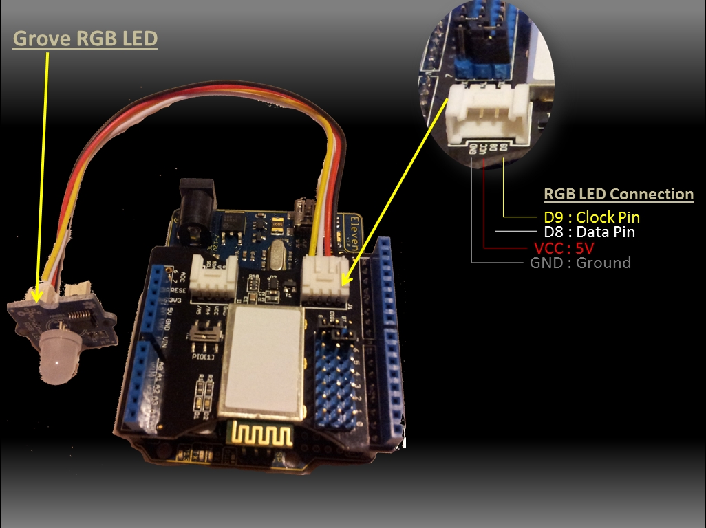
Here is a picture of the components used in this sketch:
Bluetooth Shield with Grove RGB LED


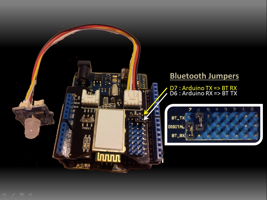
Please take notice of the Jumper pin placement on the Bluetooth Shield. This ensures communication between the Arduino and Bluetooth Shield, and is reflected in the Arduino code further down this page. The Arduino transmits information to the Bluetooth Shield on Digital pin 7, and therefore the Bluetooth Shield receivesinformation from the Arduino on Digital pin 7. On the other hand, the Bluetooth shield transmits and the Arduino receives information on Digital pin 6 (see picture below).  This serial communication between the Arduino and the Bluetooth Shield occurs through the SoftwareSeriallibrary. This is different from the Serial library used in some of my other tutorials (often to display information in the Serial Monitor). The Arduino UNO's Serial pins are 0 (RX) and 1 (TX). It is worth looking at the Arduino Serialpage if you happen to have an Arduino Leonardo, because there are some differences that you should take into consideration when running this sketch.


Jumpers on Shield


Make sure that your Arduino has the following code installed and running BEFORE you launch the Android/Processing Sketch on your Android Device. If you don't do it in this order, your Android phone will not discover the Bluetooth Device attached to the Arduino, and you will waste a lot of time. Make sure that the Bluetooth shield is flashing it's red/green LEDs. Once you see this alternating red/green LED display, launch the Android/Processing sketch on the Android device. When you see the chainable RGB LED turn from white to green, you know you have a successful connection. You may then press the GUI buttons on the Android phone to change the colour of the LED to either Red, Green, Blue or Off.

Arduino Sketch 3: Bluetooth RGB Colour Changer (with OFF option)
2
3
4
5
6
7
8
9
10
11
12
13
14
15
16
17
18
19
20
21
22
23
24
25
26
27
28
29
30
31
32
33
34
35
36
37
38
39
40
41
42
43
44
45
46
47
48
49
50
51
52
53
54
55
56
57
58
59
60
61
62
63
64
65
66
67
68
69
70
71
72
73
74
75
76
77
78
79
80
81
82
83
84
85
86
87
88
89
90
91
92
93
94
95
96
97
98
99
100
101
102
103
104
105
106
107
108
109
110
111
112
113
114
115
116
117
118
119
120
121
122
123
124
125
126
127
128
129
130
131
132
133
134
135
136
137
138
139
140
141
142
143
144
145
146
147
148
149
150
151
152
153
154
155
156
157
158
159
160
161
162
163
164
165
166
167
168
/* This project combines the code from a few different sources.
This project was put together by ScottC on the 15/01/2013
http://arduinobasics.blogspot.com/

Bluetooth slave code by Steve Chang - downloaded from :
http://www.seeedstudio.com/wiki/index.php?title=Bluetooth_Shield

Grove Chainable RGB code can be found here :
http://www.seeedstudio.com/wiki/Grove_-_Chainable_RGB_LED#Introduction

Updated on 25 March 2013: Receive 'x' to turn off RGB LED.

*/


#include <SoftwareSerial.h>
//Software Serial Port

#define uint8
unsigned char
#define uint16
unsigned int
#define uint32
unsigned long int

#define RxD 6
// This is the pin that the Bluetooth (BT_TX) will transmit to the Arduino (RxD)
#define TxD 7
// This is the pin that the Bluetooth (BT_RX) will receive from the Arduino (TxD)

#define DEBUG_ENABLED 1

int Clkpin = 9; //RGB LED Clock Pin (Digital 9)
int Datapin = 8; //RGB LED Data Pin (Digital 8)

SoftwareSerial blueToothSerial(RxD,TxD);
/*----------------------SETUP----------------------------*/ void setup() {
Serial.begin(9600);
// Allow Serial communication via USB cable to computer (if required)
pinMode(RxD, INPUT);
// Setup the Arduino to receive INPUT from the bluetooth shield on Digital Pin 6
pinMode(TxD, OUTPUT);
// Setup the Arduino to send data (OUTPUT) to the bluetooth shield on Digital Pin 7
pinMode(13,OUTPUT);
// Use onboard LED if required.
setupBlueToothConnection();
//Used to initialise the Bluetooth shield

pinMode(Datapin, OUTPUT);
// Setup the RGB LED Data Pin
pinMode(Clkpin, OUTPUT);
// Setup the RGB LED Clock pin

}
/*----------------------LOOP----------------------------*/ void loop() {
digitalWrite(13,LOW);
//Turn off the onboard Arduino LED
char recvChar;
while(1){
if(blueToothSerial.available()){//check if there's any data sent from the remote bluetooth shield
recvChar = blueToothSerial.read();
Serial.print(recvChar);
// Print the character received to the Serial Monitor (if required)

//If the character received = 'r' , then change the RGB led to display a RED colour
if(recvChar=='r'){
Send32Zero();
// begin
DataDealWithAndSend(255, 0, 0);
// first node data
Send32Zero();
// send to update data
}

//If the character received = 'g' , then change the RGB led to display a GREEN colour
if(recvChar=='g'){
Send32Zero();
// begin
DataDealWithAndSend(0, 255, 0);
// first node data
Send32Zero();
// send to update data
}

//If the character received = 'b' , then change the RGB led to display a BLUE colour
if(recvChar=='b'){
Send32Zero();
// begin
DataDealWithAndSend(0, 0, 255);
// first node data
Send32Zero();
// send to update data
}

//If the character received = 'x' , then turn RGB led OFF
if(recvChar=='x'){
Send32Zero();
// begin
DataDealWithAndSend(0, 0, 0);
// first node data
Send32Zero();
// send to update data
}
}

//You can use the following code to deal with any information coming from the Computer (serial monitor)
if(Serial.available()){
recvChar = Serial.read();

//This will send value obtained (recvChar) to the phone. The value will be displayed on the phone.
blueToothSerial.print(recvChar);
}
}
}

//The following code is necessary to setup the bluetooth shield ------copy and paste----------------
void setupBlueToothConnection()
{
blueToothSerial.begin(38400);
//Set BluetoothBee BaudRate to default baud rate 38400
blueToothSerial.print("
\r\n+STWMOD=0\r\n"); //set the bluetooth work in slave mode
blueToothSerial.print("
\r\n+STNA=SeeedBTSlave\r\n"); //set the bluetooth name as "SeeedBTSlave"
blueToothSerial.print("
\r\n+STOAUT=1\r\n"); // Permit Paired device to connect me
blueToothSerial.print("
\r\n+STAUTO=0\r\n"); // Auto-connection should be forbidden here
delay(2000);
// This delay is required.
blueToothSerial.print("
\r\n+INQ=1\r\n"); //make the slave bluetooth inquirable
Serial.println("
The slave bluetooth is inquirable!");
delay(2000);
// This delay is required.
blueToothSerial.flush();
}

//The following code snippets are used update the colour of the RGB LED-----copy and paste------------
void ClkProduce(void){
digitalWrite(Clkpin, LOW);
delayMicroseconds(20);
digitalWrite(Clkpin, HIGH);
delayMicroseconds(20);
}
void Send32Zero(void){
unsigned char i;
for (i=0; i<32; i++){
digitalWrite(Datapin, LOW);
ClkProduce();
}
}

uint8 TakeAntiCode(uint8 dat){
uint8 tmp = 0;
if ((dat & 0x80) == 0){
tmp |= 0x02;
}

if ((dat & 0x40) == 0){
tmp |= 0x01;
}

return tmp;
}
// gray data
void DatSend(uint32 dx){
uint8 i;
for (i=0; i<32; i++){
if ((dx & 0x80000000) != 0){
digitalWrite(Datapin, HIGH);
}
else {
digitalWrite(Datapin, LOW);
}

dx <<= 1;
ClkProduce();
}
}
// data processing
void DataDealWithAndSend(uint8 r, uint8 g, uint8 b){
uint32 dx = 0;

dx |= (uint32)0x03 << 30;
// highest two bits 1,flag bits
dx |= (uint32)TakeAntiCode(b) << 28;
dx |= (uint32)TakeAntiCode(g) << 26;
dx |= (uint32)TakeAntiCode(r) << 24;

dx |= (uint32)b << 16;
dx |= (uint32)g << 8;
dx |= r;

DatSend(dx);
}


Please note that this Arduino code/project will work with SeeedStudio's Bluetooth Shield.  You may need to modify the Arduino Code (lines 95-107) to coincide with your own bluetooth shield. I got the code snippet within the my setupBlueToothConnection() method from some example code from Steve Chang which was found on SeeedStudio's Bluetooth Shield Wiki page. Here is some other useful information in relation to setting up this Bluetooth Shield that could be of help in your project (here).

Much of the code used within the Android/Processing sketch was made possible through constant reference to these sites:
And I would also like to thank Pauline303 who made the suggestion within the Processing Forums to use APWidgets Library for my Buttons in the App.
The Arduino and Processing Forums are always a great place to get help in a short amount of time.


Description: Bluetooth Android Processing 4 Rating: 3.5 Reviewer: Unknown ItemReviewed: Bluetooth Android Processing 4
Bluetooth Tutorial 1 Reviewed by Unknown on 20:56 Rating: 4.5

Bluetooth Tutorial 1


Introduction:
The bluetooth shield used in this project is a great way to detach the Arduino from your computer. What is even better, is that the shield allows you to control your arduino from your mobile phone or other bluetooth enabled device through simple Serial commands. In this tutorial we will connect a Grove Chainable RGB LED to the bluetooth shield directly, and send simple commands using the Bluetooth SPP app on a Samsung Galaxy S2 to change the colour of the LED (Red , Green and Blue)


Parts Required:
Freetronics Eleven or any compatible Arduino.
Bluetooth shield
Grove Chainable RGB LED
Grove Wire connectors


The Video:


The Arduino Sketch:


Arduino Code:
You can download the Arduino IDE from this site.


 1
2
3
4
5
6
7
8
9
10
11
12
13
14
15
16
17
18
19
20
21
22
23
24
25
26
27
28
29
30
31
32
33
34
35
36
37
38
39
40
41
42
43
44
45
46
47
48
49
50
51
52
53
54
55
56
57
58
59
60
61
62
63
64
65
66
67
68
69
70
71
72
73
74
75
76
77
78
79
80
81
82
83
84
85
86
87
88
89
90
91
92
93
94
95
96
97
98
99
100
101
102
103
104
105
106
107
108
109
110
111
112
113
114
115
116
117
118
119
120
121
122
123
124
125
126
127
128
129
130
131
132
133
134
135
136
137
138
139
140
141
142
143
144
145
146
147
148
149
150
151
152
153
154
155
156
157
158
159
/* This project combines the code from a few different sources.
This project was put together by ScottC on the 15/01/2013
http://arduinobasics.blogspot.com/

Bluetooth slave code by Steve Chang - downloaded from :
http://www.seeedstudio.com/wiki/index.php?title=Bluetooth_Shield

Grove Chainable RGB code can be found here :
http://www.seeedstudio.com/wiki/Grove_-_Chainable_RGB_LED#Introduction

*/

#include <SoftwareSerial.h> //Software Serial Port

#define uint8 unsigned char
#define uint16 unsigned int
#define uint32 unsigned long int

#define RxD 6 // This is the pin that the Bluetooth (BT_TX) will transmit to the Arduino (RxD)
#define TxD 7 // This is the pin that the Bluetooth (BT_RX) will receive from the Arduino (TxD)

#define DEBUG_ENABLED 1


int Clkpin = 9; //RGB LED Clock Pin (Digital 9)
int Datapin = 8; //RGB LED Data Pin (Digital 8)

SoftwareSerial blueToothSerial(RxD,TxD);

/*----------------------SETUP----------------------------*/
void setup() {
Serial.begin(9600); // Allow Serial communication via USB cable to computer (if required)
pinMode(RxD, INPUT); // Setup the Arduino to receive INPUT from the bluetooth shield on Digital Pin 6
pinMode(TxD, OUTPUT); // Setup the Arduino to send data (OUTPUT) to the bluetooth shield on Digital Pin 7
pinMode(13,OUTPUT); // Use onboard LED if required.
setupBlueToothConnection(); //Used to initialise the Bluetooth shield

pinMode(Datapin, OUTPUT); // Setup the RGB LED Data Pin
pinMode(Clkpin, OUTPUT); // Setup the RGB LED Clock pin

}

/*----------------------LOOP----------------------------*/
void loop() {
digitalWrite(13,LOW); //Turn off the onboard Arduino LED
char recvChar;
while(1){
if(blueToothSerial.available()){//check if there's any data sent from the remote bluetooth shield
recvChar = blueToothSerial.read();
Serial.print(recvChar); // Print the character received to the Serial Monitor (if required)

//If the character received = 'r' , then change the RGB led to display a RED colour
if(recvChar=='r'){
Send32Zero(); // begin
DataDealWithAndSend(255, 0, 0); // first node data
Send32Zero(); // send to update data
}

//If the character received = 'g' , then change the RGB led to display a GREEN colour
if(recvChar=='g'){
Send32Zero(); // begin
DataDealWithAndSend(0, 255, 0); // first node data
Send32Zero(); // send to update data
}

//If the character received = 'b' , then change the RGB led to display a BLUE colour
if(recvChar=='b'){
Send32Zero(); // begin
DataDealWithAndSend(0, 0, 255); // first node data
Send32Zero(); // send to update data
}
}

//You can use the following code to deal with any information coming from the Computer (serial monitor)
if(Serial.available()){
recvChar = Serial.read();

//This will send value obtained (recvChar) to the phone. The value will be displayed on the phone.
blueToothSerial.print(recvChar);
}
}
}


//The following code is necessary to setup the bluetooth shield ------copy and paste----------------
void setupBlueToothConnection()
{
blueToothSerial.begin(38400); //Set BluetoothBee BaudRate to default baud rate 38400
blueToothSerial.print("\r\n+STWMOD=0\r\n"); //set the bluetooth work in slave mode
blueToothSerial.print("\r\n+STNA=SeeedBTSlave\r\n"); //set the bluetooth name as "SeeedBTSlave"
blueToothSerial.print("\r\n+STOAUT=1\r\n"); // Permit Paired device to connect me
blueToothSerial.print("\r\n+STAUTO=0\r\n"); // Auto-connection should be forbidden here
delay(2000); // This delay is required.
blueToothSerial.print("\r\n+INQ=1\r\n"); //make the slave bluetooth inquirable
Serial.println("The slave bluetooth is inquirable!");
delay(2000); // This delay is required.
blueToothSerial.flush();
}


//The following code snippets are used update the colour of the RGB LED-----copy and paste------------
void ClkProduce(void){
digitalWrite(Clkpin, LOW);
delayMicroseconds(20);
digitalWrite(Clkpin, HIGH);
delayMicroseconds(20);
}

void Send32Zero(void){
unsigned char i;
for (i=0; i<32; i++){
digitalWrite(Datapin, LOW);
ClkProduce();
}
}

uint8 TakeAntiCode(uint8 dat){
uint8 tmp = 0;
if ((dat & 0x80) == 0){
tmp |= 0x02;
}

if ((dat & 0x40) == 0){
tmp |= 0x01;
}

return tmp;
}

// gray data
void DatSend(uint32 dx){
uint8 i;
for (i=0; i<32; i++){
if ((dx & 0x80000000) != 0){
digitalWrite(Datapin, HIGH);
} else {
digitalWrite(Datapin, LOW);
}

dx <<= 1;
ClkProduce();
}
}

// data processing
void DataDealWithAndSend(uint8 r, uint8 g, uint8 b){
uint32 dx = 0;

dx |= (uint32)0x03 << 30; // highest two bits 1,flag bits
dx |= (uint32)TakeAntiCode(b) << 28;
dx |= (uint32)TakeAntiCode(g) << 26;
dx |= (uint32)TakeAntiCode(r) << 24;

dx |= (uint32)b << 16;
dx |= (uint32)g << 8;
dx |= r;

DatSend(dx);
}

The code above was formatted using hilite.me

Notes:
You don't need to download a library to get this project running. But if you plan to use bluetooth shields to get 2 Arduinos to communicate to each other, then I would advise that you download the library files (which are just examples) from the Seeedstudio site : here.

Visit this site to setup your phone or laptop for bluetooth communication to the shield - here

The app used on my Samsung Galaxy S2 phone was "Bluetooth SPP"

You will initially need to enter a pin of '0000' to establish a connection to the Bluetooth shield - which will appear as "SeeedBTSlave" or whatever text you place on line 90 of the Arduino code above.


Warning !

Not all phones are compatible with the bluetooth shield.
If you have used this shield before - please let me know what phone you used - so that we can build a list and inform others whether their phone is likely to work with this project or not. Obviously - those phones that do not have bluetooth within - will not work :).
And I have not tried any other apps either

I got it to work very easily with my Samsung Galaxy S2 using the free Bluetooth SPP app from the google play store.

This was fun, but I want to make my own app !
Have a look at my latest 4-part tutorial which takes you step-by-step through the process of building your own app using the Processing/Android IDE.
You can build your own GUI interface on your Android Phone and get it to communicate via Bluetooth to your Arduino/Bluetooth Shield. Click on the links below for more information:


If you like this page, please do me a favour and show your appreciation :

 
Visit my ArduinoBasics Google + page.
Follow me on Twitter by looking for ScottC @ArduinoBasics.
Have a look at my videos on my YouTube channel.


However, if you do not have a google profile...
Feel free to share this page with your friends in any way you see fit.


Description: Bluetooth Tutorial 1 Rating: 3.5 Reviewer: Unknown ItemReviewed: Bluetooth Tutorial 1
Back to top